A circumferential back pressure

A back pressure device and pressure head technology, applied in the field of pressure control, can solve the problems of large opening pressure, increase movement resistance, increase opening pressure, etc., and achieve the effect of sensitive differential pressure response, avoiding clogging of channels, and ensuring closing strength.

Active Publication Date: 2015-08-26
CHENGDU HAOHAN WELL COMPLETION & LOGGING SCI & TECH +1
View PDF7 Cites 0 Cited by
  • Summary
  • Abstract
  • Description
  • Claims
  • Application Information

AI Technical Summary

Problems solved by technology

This sealing method has the following defects: first, the medium flowing through must be clean, if there are small particles of impurities stuck on the sealing cone surface of the needle tip, the back pressure device will fail; second, the manufacturing accuracy of the product is high, The roughness and hardness of the sealing cone surface of the needle rod should be high, and the back and forth movement of the needle rod must be coaxial with the sealing needle seat, otherwise the needle tip will easily damage the sealing cone surface; the third is that the force-bearing area of ​​the inlet end is small, resulting in high opening pressure; the fourth is When the inlet pressure is too high, the elastic steel sheet is easily broken down and damaged
However, this type of back pressure device has the following defects: First, the main diaphragm material is polytetrafluoroethylene non-metallic material, which is prone to permanent deformation after long-term pressure, and the repeatability is poor; second, the pressure control accuracy is not high, and the starting pressure difference is large , the outlet flow state is unstable; the third is that this type of back pressure device has a large shape and is not easy to install
The disadvantage of this type of back pressure device is that the elasticity of the diaphragm is used to drive the up and down movement and displacement of the piston, and the piston is equipped with multi-stage sealing rings, which increases the movement resistance, which also increases the opening pressure, making the back pressure device The control accuracy is reduced, and at the same time, when the diaphragm fails, it will no longer work; the structure of this type of back pressure device is relatively complicated, and it is not easy for users to maintain

Method used


Image

  • A circumferential back pressure
  • A circumferential back pressure
  • A circumferential back pressure

Examples


Embodiment 1

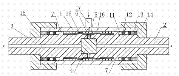
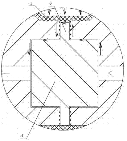
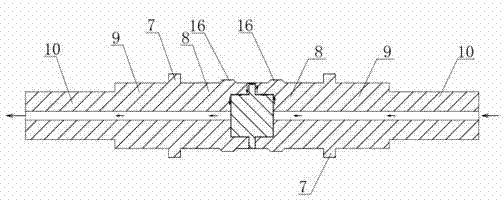
[0035]A circumferential back pressure device, comprising a sealed cylinder 1, in which a flexible sealing sleeve 5, a solid valve core 4, a back pressure joint I2 with a liquid input channel and a liquid output channel are fixed. The back pressure joint II3, the back pressure joint I2 and the back pressure joint II3 are provided with counterbore, the solid valve core 4 is clamped by the counterbore of the back pressure joint I2 and the counterbore of the back pressure joint II3, the The solid valve core 4 is provided with a valve core convex ring 6 located between the back pressure joint I2 and the back pressure joint II3; the flexible sealing sleeve 5 is set on the back pressure joint I2, the valve core convex ring 6 and the back pressure joint II3 , there is a gap between the flexible sealing sleeve 5 set on the spool convex ring 6 and the sealing cylinder 1, the back pressure joint I2, the solid spool 4, the spool convex ring 6, the back pressure joint II3 and Liquid channe...

Embodiment 2

[0040] A circumferential back pressure device, comprising a sealed cylinder 1, in which a flexible sealing sleeve 5, a solid valve core 4, a back pressure joint I2 with a liquid input channel and a liquid output channel are fixed. The back pressure joint 3II, the back pressure joint I2 and the back pressure joint II3 are provided with counterbore, the solid valve core 4 is clamped by the counterbore of the back pressure joint I2 and the counterbore of the back pressure joint II3, the The solid valve core 4 is provided with a valve core convex ring 6 located between the back pressure joint I2 and the back pressure joint II3; the flexible sealing sleeve 5 is set on the back pressure joint I2, the valve core convex ring 6 and the back pressure joint II3 , there is a gap between the flexible sealing sleeve 5 set on the spool convex ring 6 and the sealing cylinder 1, the back pressure joint I2, the solid spool 4, the spool convex ring 6, the back pressure joint II3 and Liquid chann...

Embodiment 3

[0053] The difference from Example 2 is that in the present invention, there are multiple "O"-shaped sealing rings 11 and sealing retaining rings 12, and multiple "O"-shaped sealing rings 11 and sealing retaining rings 12 are alternately distributed in the sealing cavity.


PUM


Abstract

The invention discloses a circumferential pressure return device which comprises a sealing cylinder body, flexible sealing sleeves, a solid valve element, a pressure return joint I and a pressure return joint II are fixed in the sealing cylinder body, the pressure return joint I is provided with a liquid input passage, the pressure return joint II is provided with a liquid output passage, countersinks are respectively formed in the pressure return joint I and the pressure return joint II, the solid valve element is clamped through the countersinks in the pressure return joint I and the pressure return joint II, valve element bulge loops, positioned between the pressure return joint I and the pressure return joint II, are arranged on the solid valve element, the flexible sealing sleeves are sheathed on the pressure return joint I, the valve element bulge loops and the pressure return joint II, a gap is formed between the flexible sealing sleeve sheathed on the valve element bulge loop and the sealing cylinder body, and a liquid passage is formed among the pressure return joint I, the solid valve element, the valve element bulge loops, the pressure return joint II and the flexible sealing sleeves. According to the invention, the flexible sealing manner replaces the rigid sealing manner, so that the differential pressure reaction is more sensitive, the precision can be up to 1*10<-3> MPa, and the highest working pressure of the circumferential pressure return device can be up to 60 MPa.

Description

technical field [0001] The invention relates to the technical field of pressure control, in particular to a circumferential back pressure device applicable to cement physical and mechanical performance testing equipment and indoor analytical instruments in the oil and gas industry. Background technique [0002] Back pressure control is a method often used in experiments for indoor analytical instruments in the oil and gas industry, especially when simulating various liquid experiments under high temperature and high pressure conditions in reservoirs, evaluating formation conditions, or conducting oil and gas development and recovery experiments, in order to prevent The vaporization of the high-temperature liquid at the outlet and keeping the pressure at the outlet stable are necessary conditions for the smooth progress of the experiment. According to different experimental schemes of this type of experiment, some experiments take a long time, up to several days or longer, an...

Claims


Application Information

Patent Timeline
Patent Type & Authority Patents(China)
IPC IPC(8): F16K17/02F16K47/00
Inventor 陈一健张伦平陈东
Owner CHENGDU HAOHAN WELL COMPLETION & LOGGING SCI & TECH
Why Eureka
Try Eureka