Electromagnetic micro valve integrated on micro-fluidic chip

A microfluidic chip and microvalve technology, applied in valve details, diaphragm valves, valve devices, etc., can solve problems such as unfavorable use by ordinary users, matching of portable instruments, complex technology, etc., and achieve wide application range, fast response, and easy operation good control effect

Inactive Publication Date: 2013-10-02
DALIAN MARITIME UNIVERSITY
View PDF7 Cites 18 Cited by
  • Summary
  • Abstract
  • Description
  • Claims
  • Application Information

AI Technical Summary

Problems solved by technology

Existing micro valves mainly include pneumatic valves, piezoelectric valves, phase change valves, torque valves, etc., but these valves are complicated in manufacturing technology, difficult to match with portable instruments, or cumbersome in operation, which is not conducive to ordinary users

Method used


Image

  • Electromagnetic micro valve integrated on micro-fluidic chip
  • Electromagnetic micro valve integrated on micro-fluidic chip
  • Electromagnetic micro valve integrated on micro-fluidic chip

Examples


Embodiment Construction

[0020] The technical scheme of the present invention is further described below in conjunction with accompanying drawing and specific embodiment:

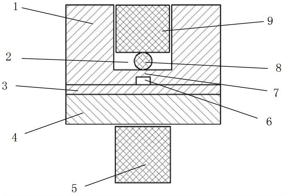
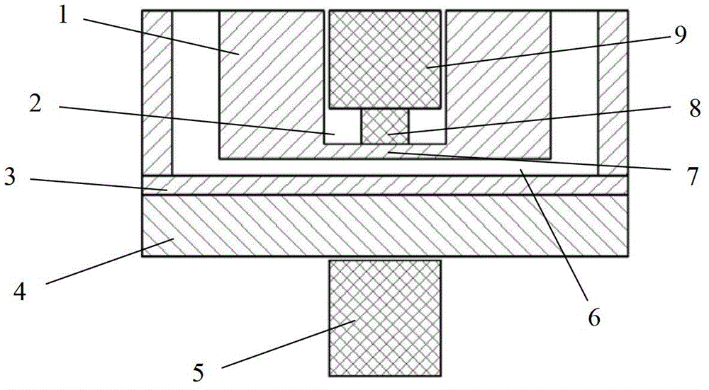
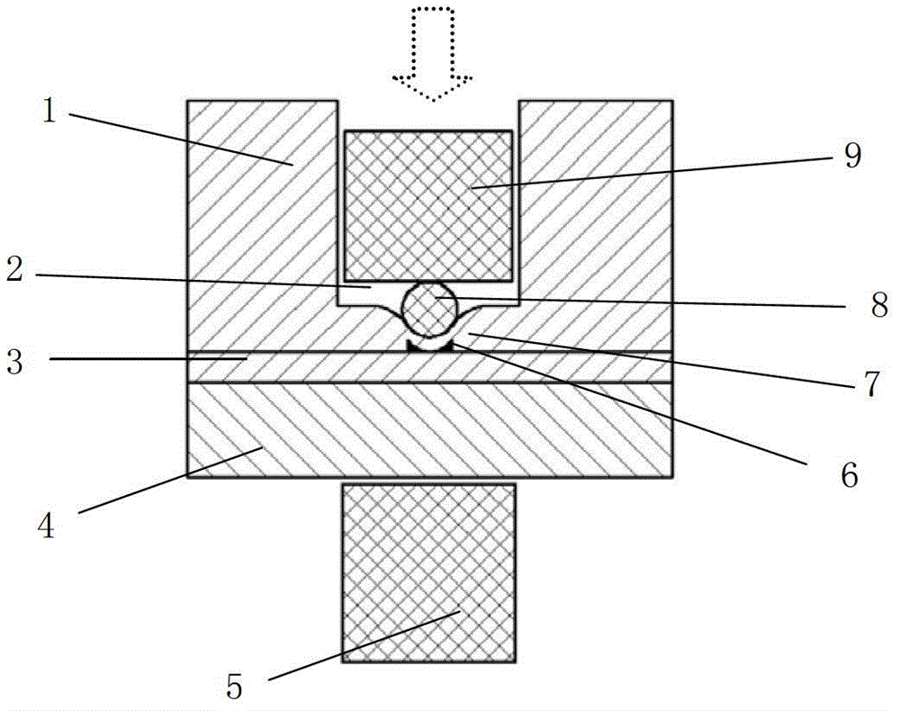
[0021] like figure 1 , figure 2 As shown, the electromagnetic microvalve integrated on the microfluidic chip provided by the present invention includes a permanent magnet 9 , an electromagnet 5 , a thimble 8 and a valve seat 2 . The microfluidic chip includes two layers, the upper layer is a PDMS chip 1, and the lower layer is a substrate 4; the substrate 4 is spin-coated with a PDMS coating 3, and the thickness of the spin coating is 0.5-1 mm; the bottom surface of the valve seat 2 is PDMS elastic film 7, and the bottom surface is the common wall where the valve seat 2 intersects with the fluid channel 6 of the microfluidic chip, the thickness of the elastic film can be 500 μm; the upper end of the valve seat communicates with the outside world; the thimble 8 is located at the PDMS elastic On the film 7, corresponding to the ce...


PUM

PropertyMeasurementUnit
Thicknessaaaaaaaaaa
Thicknessaaaaaaaaaa

Abstract

The invention relates to an electromagnetic micro valve integrated on a micro-fluidic chip. The micro-fluidic chip is formed by a chip with a fluid flow passage and a substrate. The electromagnetic micro valve integrated on the micro-fluidic chip is characterized in that the micro valve comprises a permanent magnet, an electromagnet, an ejector pin and a valve seat, wherein the valve seat is a concave hole which is machined in the chip and located above the fluid flow passage, the valve seat bottom face is a PDMS elastic thin film, the bottom face is a shared wall where the valve seat and the fluid flow passage intersect, the upper end of the valve seat is communicated with the outside world, the ejector pin is arranged in the center of the valve seat bottom face and located over the fluid flow passage, the permanent magnet is arranged in the valve seat and located over the ejector pin, and the electromagnet is arranged below the substrate and located under the permanent magnet. The electromagnetic micro valve integrated on the micro-fluidic chip can respond full-automatically and rapidly, and has the advantages of being simple in design, good in operation and controlling performance, wide in application range and capable of achieving the on and off of the conveying of specific passage fluid in a full automatic and programmed mode.

Description

technical field [0001] The invention relates to the technical field of microfluidic chips, in particular to a thimble-type electromagnetic microvalve structure integrated on a microfluidic chip. Background technique [0002] The microfluidic chip is based on the micro-electromechanical processing technology. By constructing complex micro-channels on the chip, the controllable micro-fluid runs through the entire system and completes various biological and chemical processes. In the early stage of the development of microfluidic chip technology, chip capillary electrophoresis was the mainstream technology, and the chip used was simple in structure and single in function; Important biological and chemical processes such as reaction and cell lysis have become new hotspots, and in order to study these complex biochemical reactions, it is usually necessary to fabricate many independent and uniform reaction pools on the chip, that is, to construct microreactor arrays. [0003] The...

Claims


Application Information

Patent Timeline
IPC IPC(8): F16K31/08F16K7/12B01L3/00
Inventor 李梦琪宋永欣李冬青潘新祥
Owner DALIAN MARITIME UNIVERSITY
Why Eureka
Try Eureka