Dynamic distributed Brillouin optical fiber sensing device and method

A kind of optical fiber sensing and distributed technology, applied in the field of optics, can solve the problems of small strain measurement range of dynamic sensing technology, achieve distributed Brillouin dynamic sensing, large strain measurement range, and solve fast scanning problems Effect

Active Publication Date: 2013-10-02
HARBIN INST OF TECH
View PDF3 Cites 19 Cited by
  • Summary
  • Abstract
  • Description
  • Claims
  • Application Information

AI Technical Summary

Problems solved by technology

[0003] The purpose of the present invention is to solve the problem of small strain measurement range based on the Brillouin gain slope method dynamic sensing technology, and to provide a dynamic distributed Brillouin optical fiber sensing device and method with a large measurement range

Method used


Image

  • Dynamic distributed Brillouin optical fiber sensing device and method
  • Dynamic distributed Brillouin optical fiber sensing device and method
  • Dynamic distributed Brillouin optical fiber sensing device and method

Examples


specific Embodiment approach 1

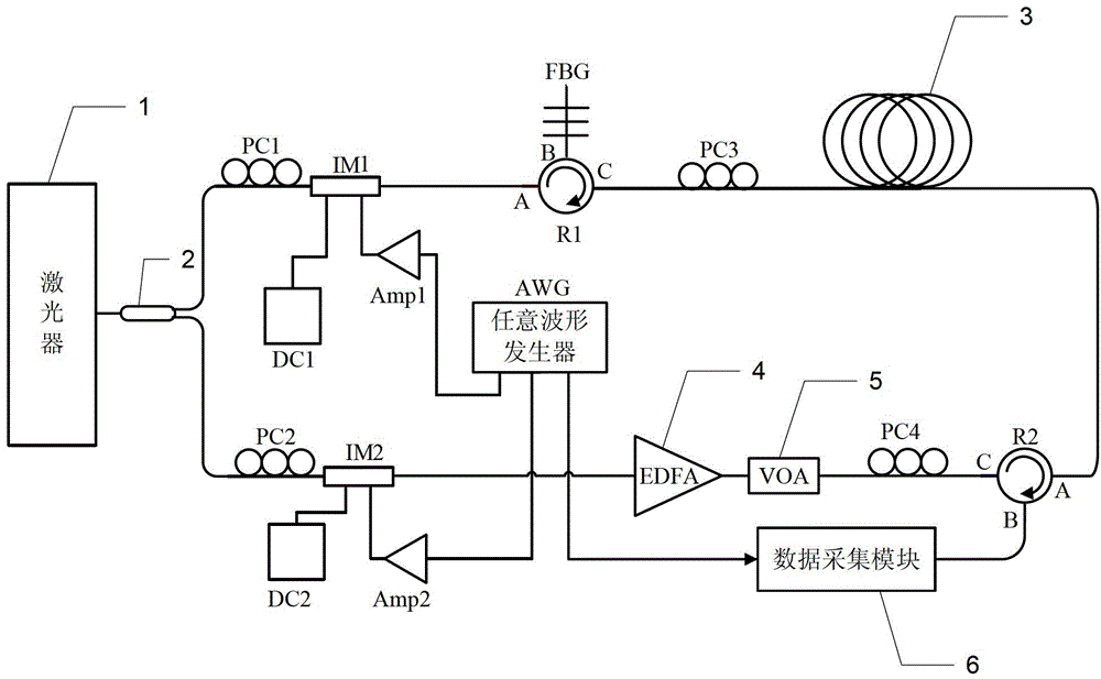
[0027] Specific implementation mode one: the following combination figure 1 and figure 2 Describe this embodiment, the dynamic distributed Brillouin optical fiber sensing device described in this embodiment, it comprises laser 1, coupler 2, polarization maintaining fiber 3 to be tested, erbium-doped fiber amplifier 4, adjustable optical attenuator 5, Data acquisition module 6, first polarization controller PC1, second polarization controller PC2, third polarization controller PC3, fourth polarization controller PC4, probe light intensity modulator IM1, pump light intensity modulator IM2, any Waveform generator AWG, first circulator R1, second circulator R2, first signal amplifier Amp1 and second signal amplifier Amp2,

[0028] The RF signal output terminal of the arbitrary waveform generator AWG is connected to the modulation terminal of the probe light intensity modulator IM1 through the first signal amplifier Amp1; the rectangular pulse signal output terminal of the arbitr...

specific Embodiment approach 2

[0036] Specific implementation mode two: the following combination figure 2 This embodiment will be described. This embodiment will further describe the first embodiment, which also includes a first DC power supply DC1 and a second DC power supply DC2.

[0037] The first DC power supply DC1 provides DC working power for the probe light intensity modulator IM1;

[0038] The second DC power supply DC2 provides DC working power for the pumping optical intensity modulator IM2.

specific Embodiment approach 3

[0039]Specific implementation mode three: the following combination Figures 1 to 3 Describe this embodiment, this embodiment is based on the method for the dynamic distributed Brillouin optical fiber sensing device described in Embodiment 1, and this method comprises the following steps:

[0040] Step 1. The coupler 2 splits the laser beam into two beams, one of which is modulated into probe light by probe light intensity modulator IM1, and the other beam is modulated into pump light by pump light intensity modulator IM2.

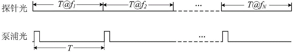
[0041] The radio frequency signal input to the modulation terminal of the probe optical intensity modulator IM1 is a wave train with N frequency step changes

[0042] f m ( t ) = f m 0 + [ t T ] f s ...


PUM


Abstract

The invention discloses a dynamic distributed Brillouin optical fiber sensing device and method, belongs to the optical field, and solves the problem of small strain measurement range in a dynamic sensing technology based on a Brillouin gain slope method. The dynamic distributed Brillouin optical fiber sensing device comprises a laser, a coupler, a to-be-measured polarization maintaining optical fiber, an erbium-doped fiber amplifier, an adjustable optical attenuator, a data acquisition module, a first polarization controller PC1, a second polarization controller PC2, a third polarization controller PC3, a fourth polarization controller PC4, a probe light intensity modulator IM1, a pump light intensity modulator IM2, an arbitrary waveform generator (AWG), a first circulator R1, a second circulator R2, a first signal amplifier Amp1 and a second signal amplifier Amp2. According to the invention, the intensity modulators can be driven by arbitrary waves, so that the frequency agility of probe light is realized, the fast frequency scan problem is solved, the distributed Brillouin dynamic sensing is achieved, and the strain of the to-be-measured polarization maintaining optical fiber is measured.

Description

technical field [0001] The invention relates to a dynamic distributed Brillouin optical fiber sensing device and method, belonging to the field of optics. Background technique [0002] Distributed dynamic sensing technology is used for distributed monitoring of transient signals. This sensing technology can realize fast and real-time measurement of the stress information of the monitored object. This sensing technology can be used to monitor the health status of infrastructure such as bridges, and can also be used to study the impact of external transient conditions such as explosions and earthquakes on the structure of the monitored object. In the traditional Brillouin optical time-domain analysis (BOTDA) technology, the frequency scanning speed is lower than the signal change, which makes the traditional BOTDA technology only suitable for the monitoring of steady-state signals, not suitable for transient signals. The existing BOTDA technology that can be used to measure ...

Claims


Application Information

Patent Timeline
Patent Type & Authority Applications(China)
IPC IPC(8): G01D5/26
Inventor 董永康姜桃飞巴德欣吕志伟
Owner HARBIN INST OF TECH
Why Eureka
Try Eureka