PLC opto-isolator driving circuit and resistance loop device of MOS gate

A resistance loop, optocoupler drive technology, applied in circuit devices, emergency protection circuit devices, emergency protection circuit devices for limiting overcurrent/overvoltage, etc., can solve the problem of PLC optocoupler being affected by bypass capacitors, etc. Achieve the effect of eliminating the influence of parasitic circuits and their bypass capacitors, increasing the current, and reducing the discharge time

Active Publication Date: 2013-10-02
STATE GRID CORP OF CHINA +2
View PDF1 Cites 0 Cited by
  • Summary
  • Abstract
  • Description
  • Claims
  • Application Information

AI Technical Summary

Problems solved by technology

[0004] The purpose of the present invention is to provide a MOS gate PLC optocoupler drive circuit and resistance loop

Method used


Image

  • PLC opto-isolator driving circuit and resistance loop device of MOS gate

Examples


Example Embodiment

[0013] The present invention will be further described in detail below in conjunction with the drawings.

[0014] Examples of MOS gate PLC optocoupler drive circuit:

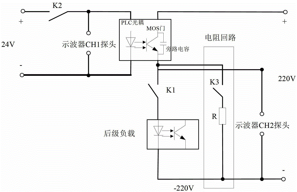
[0015] The MOS gate PLC optocoupler circuit of the present invention includes a PLC optocoupler terminal configured with a MOS gate circuit. A resistance loop is connected in parallel at both ends of the downstream load of the PLC optocoupler terminal. The resistance loop consists of a switch and a resistor. Series composition.

[0016] Such as figure 1 As shown, K2 is the primary control switch of the PLC optocoupler, K1 is the control switch of the downstream load loop, and the resistance loop is composed of resistor R and switch K3 in series. In this embodiment, the downstream load is a PLC optocoupler, switch K3 It is a switch, the resistance circuit is connected in parallel with the two ends of the PLC optocoupler of the subsequent stage. The resistance circuit has the function of eliminating the short-time cond...


PUM


Abstract

The invention relates to a PLC opto-isolator driving circuit and a resistance loop device of an MOS gate. The PLC opto-isolator driving circuit comprises a PLC opto-isolator terminal equipped with an MOS gate circuit, a resistance loop is connected in parallel with the two ends of a rear-stage load of the PLC opto-isolator terminal, the resistance loop is formed by connecting a switch and a resistor in series, the resistance loop device is formed by the resistance loop, one end of a resistor is welded to one end of the switch, the other ends of the resistor and the switch are correspondingly connected to two conductive terminals of the resistance loop device, and the resistance loop device is used for being mounted at the two ends of the rear-stage load of the PLC opto-isolator terminal of the MOS gate via the conductive terminals. With the arrangement of the resistance loop, the phenomenon of transient switch-on of a PLC opto-isolator is avoided, the discharging time of an MOS gate circuit is shortened, and the influence of a parasitic circuit and a bypass capacitor of the MOS gate is eliminated.

Description

technical field [0001] The invention relates to the field of high-voltage direct current transmission control and protection, in particular to a MOS gate PLC optocoupler drive circuit and a resistance loop device. Background technique [0002] Due to the fast signal transmission speed of the MOS gate circuit, PLC optocoupler terminals designed with such MOS gates are widely used in the interface design of HVDC control and protection systems. Due to the continuous change of current caused by the opening and closing of the MOS gate, these constantly changing currents flow through the wires and printed boards, resulting in voltage changes. In the electronic design circuit of the MOS gate element, in order to ensure that the voltage of the MOS element does not change drastically with the current, a bypass capacitor is added to the MOS gate to filter out high-frequency interference signals. [0003] Due to the influence of the parasitic circuit of the MOS gate itself and the byp...

Claims


Application Information

Patent Timeline
IPC IPC(8): H02H9/00H02H9/04
Inventor 杨广羽刘敏刘高峰王清坚霍鹏飞邹卓霖
Owner STATE GRID CORP OF CHINA
Why Eureka
Try Eureka