Width-direction end position measuring device for band-shaped member, width-direction center position measuring device for band-shaped member, and microwave scattering plate

A technology for measuring device and end position, which is applied to measuring devices, utilizing wave/particle radiation, reflection/re-radiation of radio waves, etc. Reduce and other problems, to achieve the effect of excellent environmental resistance and efficient scattering

Inactive Publication Date: 2013-10-02
NIRECO CORP
View PDF7 Cites 1 Cited by
  • Summary
  • Abstract
  • Description
  • Claims
  • Application Information

AI Technical Summary

Problems solved by technology

[0005] However, if the electromagnetic wave type device is used in a closed space below a predetermined size such as a narrow furnace, there is a problem that the measurement accuracy of the electromagnetic wave type device is reduced due to noise caused by electromagnetic waves reflected by the inner surface of the closed space.
However, the electromagnetic wave absorber has poor environmental resistance such as heat resistance, and cannot be used in a high-temperature furnace, for example.

Method used


Image

  • Width-direction end position measuring device for band-shaped member, width-direction center position measuring device for band-shaped member, and microwave scattering plate
  • Width-direction end position measuring device for band-shaped member, width-direction center position measuring device for band-shaped member, and microwave scattering plate
  • Width-direction end position measuring device for band-shaped member, width-direction center position measuring device for band-shaped member, and microwave scattering plate

Examples


Embodiment Construction

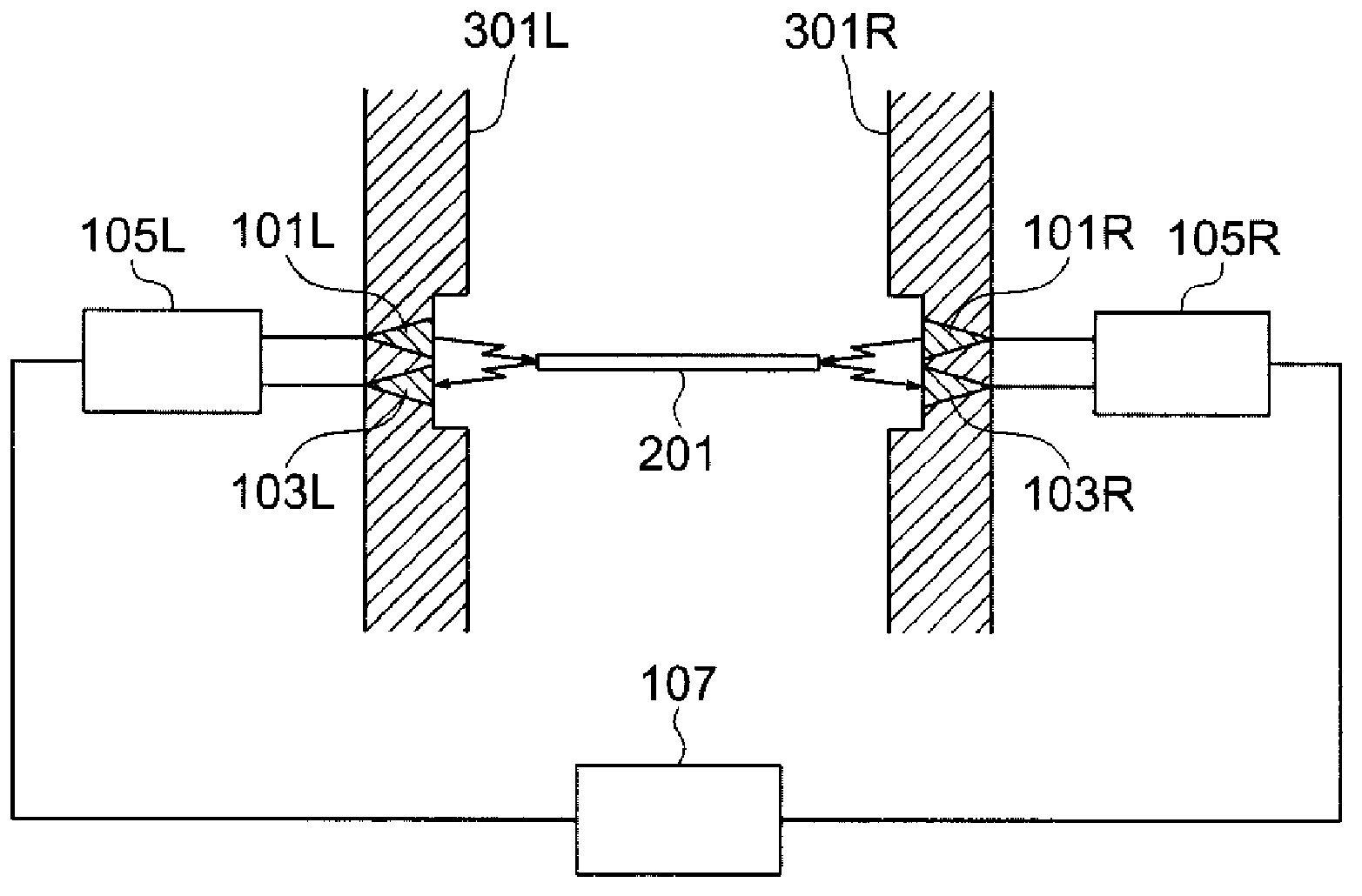
[0059] figure 1 It is a figure for explaining the width direction center position measuring apparatus of a strip-shaped object. figure 1 Diffuser plates are not documented, so figure 1 The electromagnetic wave device has the same structure as that described in Patent Document 1. The diffusion plate will be described in detail later.

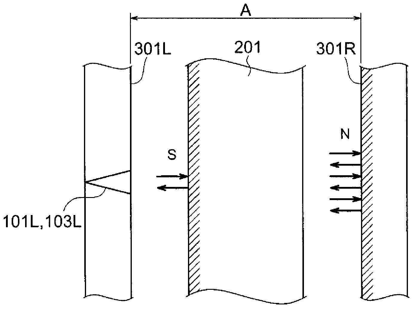
[0060] The cold-rolled steel sheet 201 as a strip passes between the continuous annealing furnace walls 301R, 301L as a closed space. Here, the closed space refers to a space formed by a plurality of surfaces surrounding the belt-shaped body 201 within a certain distance in the longitudinal direction of the belt-shaped body 201 . The closed space has openings serving as inlets and outlets of the strip-shaped body. The left and right directions in the figure show the width direction of the cold-rolled steel sheet 201 , and the cold-rolled steel sheet 201 travels from the front to the rear of the sheet.

[0061] The right furnace wall 301R is ...


PUM


Abstract

This width-direction end position measuring device is a width-direction end position measuring device for measuring the position of a width-direction end of a band-shaped member that passes through an enclosed space surrounded by a plurality of surfaces. This width-direction end position measuring device is provided with antennas for radiating electromagnetic waves toward the width-direction end and receiving electromagnetic waves reflected by the width-direction end, respectively, a signal processing unit for finding the position of the width-direction end using information relating to the reflected electromagnetic waves, and a scattering plate for scattering incident electromagnetic waves, the antennas are installed on a first surface of the enclosed space, the first surface facing the width-direction end the position of which is to be found, and the scattering plate is installed on a second surface facing the first surface.

Description

technical field [0001] The present invention relates to a device for measuring the end position in the width direction of a strip, a device for measuring the center position in the width direction of a strip, and a microwave scattering plate. Background technique [0002] In the production / processing steps of strips such as steel sheets (also referred to as steel strips), it is necessary to control the strips so that they do not meander. In addition, when winding the strip-shaped body around the coil, it is necessary to control the end of the strip-shaped body wound at the winding position of the coil to a fixed position in order to conform to the winding shape of the coil. For such control, a strip-shaped body widthwise end position measuring device and a strip-shaped body widthwise center position measuring device are used in the strip-shaped body production / processing process. [0003] As these widthwise edge position measuring devices and widthwise center position measu...

Claims


Application Information

Patent Timeline
Patent Type & Authority Applications(China)
IPC IPC(8): G01B15/00G01S13/88
CPCG01B15/04G01S13/325G01S13/88B65H26/00G01B15/00G01S13/06
Inventor 山本昌弘山仓崇宽加藤裕雅中尾友纪
Owner NIRECO CORP
Why Eureka
Try Eureka