Laboratory testing method for multi-field-of-view star sensor

A technology of star sensor and testing method, which is applied in the direction of instruments, measuring devices, etc., to achieve the effect of increasing versatility and reducing costs

Active Publication Date: 2013-10-09
HARBIN INST OF TECH
View PDF4 Cites 24 Cited by
  • Summary
  • Abstract
  • Description
  • Claims
  • Application Information

AI Technical Summary

Problems solved by technology

[0006] However, since a multi-field star sensor contains multiple (at least two) optical systems, and due to the requirements of attitude information fusion of the multi-field star sensor, the star images taken between these fields are not only The same time is required, and the star maps taken must satisfy a certain geometric relationship. Therefore, the method of shooting the same optical multi-satellite simulator for all fields of view cannot be used to test the system of the multi-satellite simulator, and the multi-view system is tested in the field Before the field star sensor, the electronic system, algorithm, optics and other functions of the multi-field star sensor must be tested in the laboratory, so a method for testing the multi-field star sensor must be designed

Method used


Image

  • Laboratory testing method for multi-field-of-view star sensor
  • Laboratory testing method for multi-field-of-view star sensor
  • Laboratory testing method for multi-field-of-view star sensor

Examples


Embodiment 1

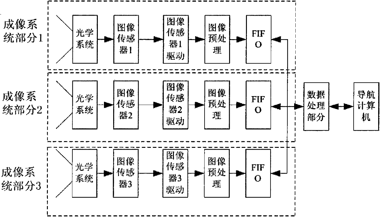
[0042]Like the single-field star sensor, the multi-field star sensor (here the three-field star sensor is used as an example to illustrate the multi-field star sensor test method, the same below) is mainly divided into two parts in terms of system composition : Imaging system part and data processing part. If the imaging system part contains two, it is called a dual-field star sensor, if the imaging system part contains three, it is called a three-field star sensor, and so on. Generally, there will be no more than three imaging systems, and all imaging systems share A data processing part, each imaging system part includes an optical system module, a detector module and a detector driver module. Each detector driving module separately controls the control timing signal of the image sensor and the star map preprocessing circuit, which is generally implemented by an FPGA chip. After preprocessing, multiple star images are sent to the data processing part of the star sensor thro...

Embodiment 2

[0074] Main performance indicators of star sensor:

[0075] Field of View: 14°×14°

[0076] Area array: 1024×1024

[0077] Detected magnitude: 6Mv

[0078] Data update rate: 15Hz

[0079] Parameters of the first multi-satellite simulator, the second multi-satellite simulator and the third multi-satellite simulator:

[0080] Field of view (°): 14×14 (software can be adjusted, the actual displayed field of view is the field of view of the simulation software)

[0081] Spectral range: visible light band 0.42-0.75

[0082] Resolution (pixels): 1024×1024

[0083] Single star resolution: better than 40″

[0084] Contrast ratio: 2000:1

[0085] Simulated magnitude (Mv): 0-9

[0086] Image display refresh rate (Hz): 50-80

[0087]We selected a certain model of three-field star sensor. The models of the three multi-satellite simulators are all SSM-1. The dynamics simulation computer and the signal lines of the three multi-star simulators of SSM-1 make the first field of view ...

Embodiment 3

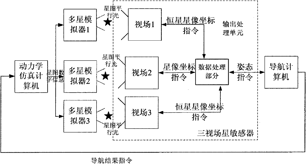
[0093] Such as Figure 7 As shown, this embodiment is an implementation of a multi-field star sensor laboratory testing method. In order to further improve the real-time performance of data transmission, all signal transmissions use LVDS electrical characteristics, and the navigation computer transmits navigation result instructions through LVDS For the dynamics simulation computer, the dynamics simulation computer decodes after receiving the navigation result instruction, and the orbit recursion algorithm of the dynamics simulation computer is realized by ARM, because the ARM processing is serial, and the three The field of view must receive the star map parallel light signal of the star simulator at the same time, and the FPGA processing is parallel, so the ARM sends the calculation result to the FPGA, and the FPGA simultaneously sends the star map signals of the three fields of view to the Multi-satellite simulator, multi-satellite simulator adopts SSM-1 type, the contrast ...


PUM


Abstract

The invention relates to a laboratory testing method for a multi-field-of-view star sensor. The method comprises the steps that: a dynamics simulation computer respectively generates fixed star maps of a first field of view, a second field of view and a third field of view according to the initial track parameter set by a user, track dynamics, installation direction between the first field of view and an aircraft, installation direction between the second field of view and the sircraft and installation direction the third field of view and the aircraft, and concurrently sends the generated fixed star maps to a first multi-star simulator, a second multi-star simulator and a third multi-star simulator through a VGA (Video Graphics Array), all the fields of view of the multi-field-of-view star sensor respectively shoot the star maps and conduct integration calculation. The practical testing environment of an external field can be entirely simulated through using the testing method, and therefore, the reliability, robustness and the like of the multi-field-of-view star sensor can be tested. The accuracy of the rolling angles of the multi-field-of-view star sensor can be improved by adopting the data integration method, in addition, the method can be used for testing a single-field-of-view star sensor, and therefore, the university of testing equipment can be improved, and the equipment testing cost can be lowered.

Description

technical field [0001] The invention relates to a laboratory testing method for a multi-field star sensor. Background technique [0002] The star sensor is a high-precision attitude measurement instrument with the celestial coordinate system as the reference system and the star as the detection target. It provides high-precision attitude information for various spacecraft such as satellites and deep space probes. The star sensor is an attitude measurement instrument integrating optics, electronics, mechanics, image processing and many other disciplines. It is mainly composed of a mechanical structure unit, an optical imaging unit and an electrical signal processing unit. In order to have a certain degree of sensitivity for a single-field star sensor, the data update rate is generally not very high. In addition, due to the limitation of the star sensor's own structure, the accuracy of its roll angle is low, which is generally about an order of magnitude lower than the yaw an...

Claims


Application Information

Patent Timeline
Patent Type & Authority Applications(China)
IPC IPC(8): G01C25/00
Inventor 王常虹李葆华
Owner HARBIN INST OF TECH
Why Eureka
Try Eureka