Separate type wave surface conversion scanning device of direct-vision synthetic aperture laser imaging radar

A synthetic aperture laser and imaging radar technology, used in radio wave measurement systems, instruments, etc., can solve the problems of large vibration influence of airborne platforms, large transmission loss, large wave surface error, etc., to achieve simple and reliable structure, small transmission loss, Guaranteed effect of accuracy

Active Publication Date: 2013-10-09
SHANGHAI INST OF OPTICS & FINE MECHANICS CHINESE ACAD OF SCI
View PDF2 Cites 11 Cited by
  • Summary
  • Abstract
  • Description
  • Claims
  • Application Information

AI Technical Summary

Problems solved by technology

The wavefront conversion scanner based on the space propagation design of the cylindrical mirror has the following problems: (1) Due to the use of spatial diffraction propagation, the wavefront conversion scanner for the entire emitted beam is bulky, with large transmission loss and great vibration of the airborne platform; (2) Since the quadratic term of the required phase is generated by spatial diffraction, the error of the obtained wave surface is large; (3) The change of the radar working mode and performance needs to change the phase distribution function of the light field in the transmitting system. At this time, it is necessary to Change the optical and mechanical structure of the entire wavefront conversion scanner, poor applicability

Method used


Image

  • Separate type wave surface conversion scanning device of direct-vision synthetic aperture laser imaging radar
  • Separate type wave surface conversion scanning device of direct-vision synthetic aperture laser imaging radar
  • Separate type wave surface conversion scanning device of direct-vision synthetic aperture laser imaging radar

Examples


Embodiment Construction

[0033] The present invention will be described in further detail below in conjunction with the accompanying drawings and embodiments, but the protection scope of the present invention should not be limited thereby.

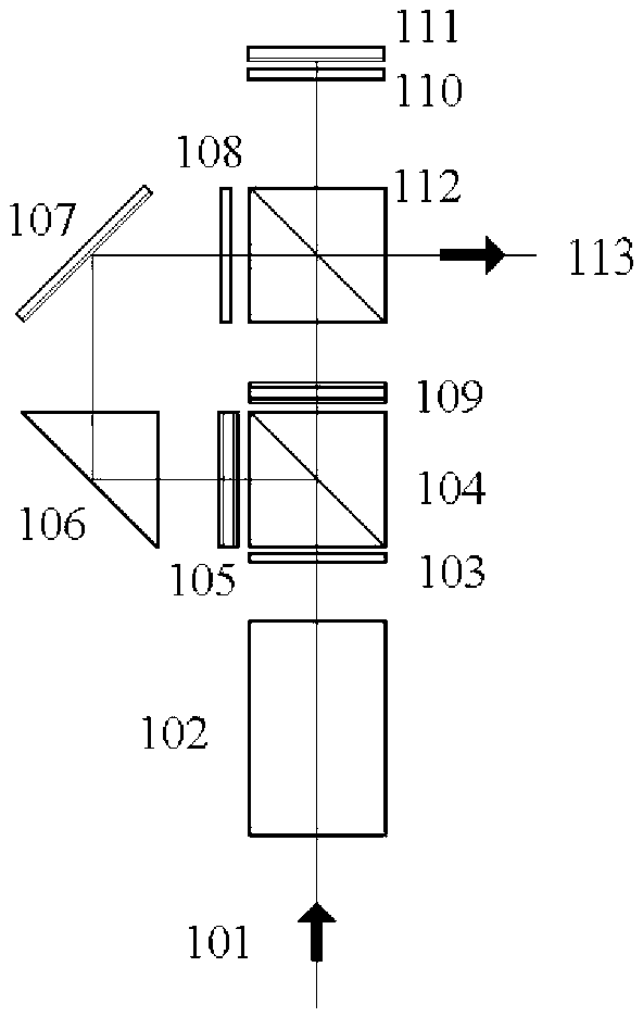
[0034] see first figure 1 , figure 1 It is the overall structural diagram of the separate wave front conversion scanning device of the direct-looking synthetic aperture laser imaging radar in Embodiment 1 of the present invention. It consists of a transform scanning structure and a along-track to orthogonally polarized wavefront transform structure.

[0035] figure 1 Among them, 101 is an incident laser beam, 102 is a cross-track to wavefront conversion scanning structure, and others are along-track to orthogonal polarization wavefront conversion structures. The structure of the separated wavefront transformation scanning device along the track to the orthogonal polarization wavefront transformation includes an incident wave plate 103, an incident polarization ...


PUM


Abstract

The invention discloses a separate type wave surface conversion scanning device of a direct-vision synthetic aperture laser imaging radar. The separate type wave surface conversion scanning device is placed between a laser light source and a transmitting primary mirror and is composed of a cross-track direction wave surface conversion scanning structure and an along-track direction orthogonal polarization wave surface conversion structure. According to the theory, the cross-track direction wave surface conversion scanning structure converts and scans a cross-track direction wave surface generated by an incident beam wave surface by means of a movement method of single cylindrical lens translation or reflecting mirror deflection, the along-track direction orthogonal polarization wave surface conversion structure further decomposes the incident beam wave surface into two orthogonal polarized separated space channels, an along-track direction cylindrical mirror is arranged in each channel to conduct wave surface conversion and wave surface reversal, two coaxial polarized orthogonal scanning transmitting wave surfaces are synthesized, and finally the two scanning transmitting wave surfaces are directly imaged onto a target surface through a transmitting optic primary mirror. The direct-vision synthetic aperture laser imaging radar separate wave surface conversion scanning device has the advantages of being simple and reliable in structure, and capable of achieving two wave surface bidirectional scanning through one drive and conveniently changing the operating performance parameters of radar by the adoption of cylindrical mirrors with different focal lengths or different deflection ranges of a reflecting mirror.

Description

technical field [0001] The invention relates to a laser emitting system for a direct-looking synthetic aperture laser imaging radar, which is a device for directly using optical elements to perform wave-front transformation and scanning on a light beam. The principle is that the cross-track to wavefront transformation scanning structure uses a single cylindrical lens translation or mirror deflection movement method to generate cross-rail to wavefront transformation and scanning of the incident beam wavefront, and the along-track to orthogonal polarization wavefront transformation structure further It is decomposed into two spatial channels separated by orthogonal polarization, and a cylindrical mirror along the track is placed in each channel to perform wavefront transformation and wavefront inversion, and then two coaxial polarization orthogonal scanning emission wavefronts are synthesized, and finally through the emission The optical primary mirror is directly imaged to the ...

Claims


Application Information

Patent Timeline
Patent Type & Authority Applications(China)
IPC IPC(8): G01S7/484G01S7/491
Inventor 刘立人
Owner SHANGHAI INST OF OPTICS & FINE MECHANICS CHINESE ACAD OF SCI
Why Eureka
Try Eureka