Ultrasonic location system and electronic device with locating function
An electronic device and ultrasonic positioning technology, applied in the field of information processing, can solve the problems of limited application scope and application environment, high clock frequency of signal processing chips, high power consumption, etc., to achieve the best user experience, low cost, and reduced power consumption. Effect
- Summary
- Abstract
- Description
- Claims
- Application Information
AI Technical Summary
Problems solved by technology
Method used
Image

Examples
no. 1 example
[0114] The first embodiment: the present invention is applied in the mobile phone:
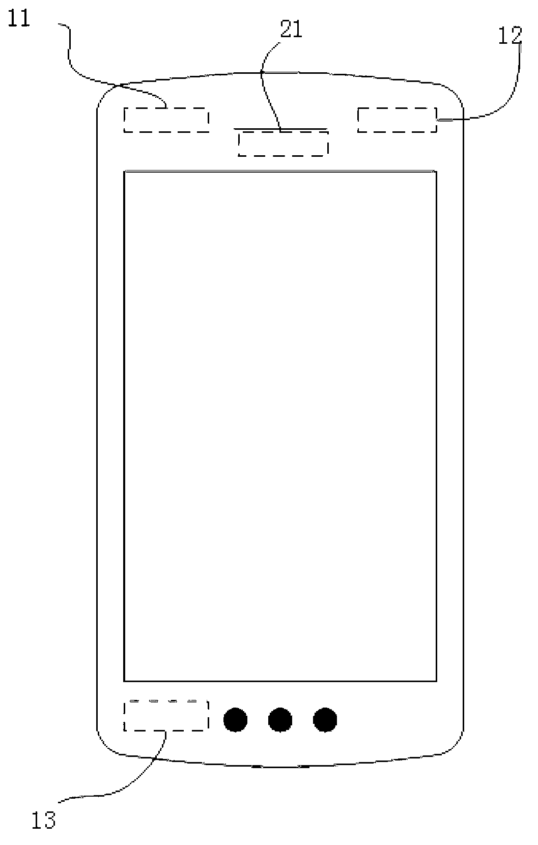
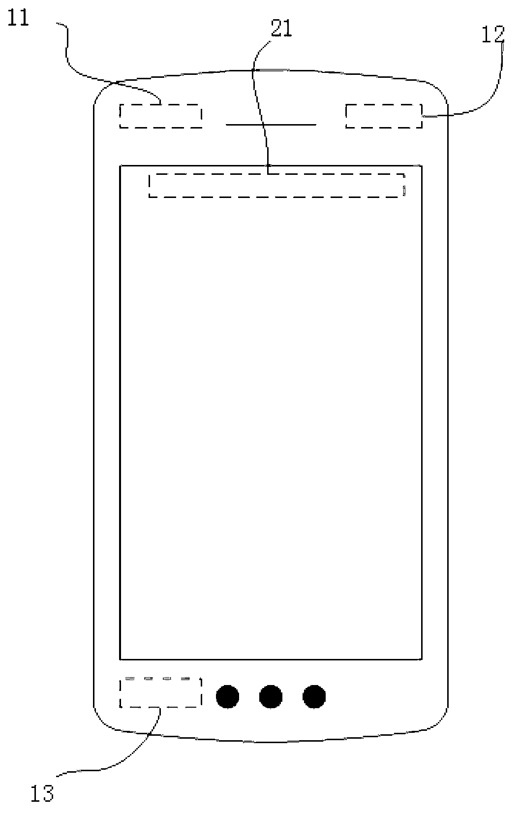
[0115] refer to figure 2 , 3, 4 to describe the first embodiment. exist figure 2 , 3, 4, capacitor electret type ECM microphones 11, 12, 13 are produced by AAC company, the parameters are 4mm in diameter, 1.6mm in height, the working frequency range of the microphone is 50Hz ~ 40kHz; the typical sensitivity is -32dBV / Pa.
[0116] exist figure 2 Among them, the parameters of the dynamic receiver 21 are 7mm*10mm*2.0mm, its working frequency range is 300Hz~40kHz, and its typical sensitivity is 105dBSPL1mW (IEC318 artificial ear test); image 3 The winning number 21 shows a 5mm*25mm*0.1mm multilayer piezoelectric ceramic chip; Figure 4 The middle symbol 21 shows a PVDF film with a thickness of 20um.
[0117] refer to figure 2 , 3, 4, condenser electret type ECM microphones 11, 12, 13 are respectively arranged on the upper left, upper right and lower left of the mobile phone. The capaci...
no. 2 example
[0121] Second embodiment: the present invention is applied in tablet computer:
[0122] refer to Figure 5 , 6, 7 to describe the second embodiment. refer to Figure 5 , 6, 7, condenser electret type ECM microphones 11, 12, 13 are produced by AAC company, the parameters are 4mm diameter, 1.6mm height, the working frequency range of the microphone is 50Hz~40kHz; the typical sensitivity is -32dBV / Pa.
[0123] Figure 5 Among them, the label 21 is a 14mm*25mm*3.0mm dynamic speaker, its working frequency range is 100Hz~40kHz, and its typical sensitivity is 75dBSPL1W / 1m (IEC268 standard baffle free field test); Figure 6 Among them, the label 21 is a 5mm*50mm*0.1mm multilayer piezoelectric ceramic sheet; Figure 7 Among them, the number 21 is a PVDF film with a thickness of 20um.
[0124] refer to Figure 5 , 6, 7, microphones 11, 12, 13 are respectively arranged on the upper left, lower left and lower right of the device. The microphones 12 and 13 are located at the bottom ...
no. 3 example
[0128] The third embodiment: applying the present invention in a flat panel TV
[0129] refer to Figure 8 , 9, 10 to describe the third embodiment. refer to Figure 8 , 9, 10, condenser electret ECM microphones 11, 12, 13 are produced by AAC company, the parameters are 4mm in diameter;
[0130] Figure 8 Among them, the label 21 is a 20mm*40mm*4.0mm dynamic speaker, its working frequency range is 500Hz~40kHz, and its typical sensitivity is 80dBSPL1W / 1m (IEC268 standard baffle free field test); Figure 9 Among them, the label 21 is a 10mm*80mm*0.1mm multilayer piezoelectric ceramic sheet; Figure 10Among them, the number 21 is a PVDF film with a thickness of 20um.
[0131] Referring to illustrations 8, 9, and 10, microphones 11, 12, and 13 are respectively arranged on the upper right, lower left, and lower right of the device. The microphones 12 and 13 are located at the bottom of the screen, corresponding to the X-axis in the coordinates, and the microphones 11 and 12 a...
PUM
| Property | Measurement | Unit |
|---|---|---|
| Sensitivity | aaaaa | aaaaa |
Abstract
Description
Claims
Application Information
 - Generate Ideas
- Intellectual Property
- Life Sciences
- Materials
- Tech Scout
- Unparalleled Data Quality
- Higher Quality Content
- 60% Fewer Hallucinations
Browse by: Latest US Patents, China's latest patents, Technical Efficacy Thesaurus, Application Domain, Technology Topic, Popular Technical Reports.
© 2025 PatSnap. All rights reserved.Legal|Privacy policy|Modern Slavery Act Transparency Statement|Sitemap|About US| Contact US: help@patsnap.com