Eureka AIR delivers breakthrough ideas for toughest innovation challenges, trusted by R&D personnel around the world.

Light guiding body structure and manufacturing method thereof

A production method and technology for light guides, applied in the directions of light guides, optics, optical components, etc., can solve the problems affecting the appearance of products, softening and deformation of light guides, dead lights, etc., to achieve good light output, quality assurance, and improved aesthetics. Effect

Active Publication Date: 2013-10-09
DONGGUAN JIAN GUAN PLASTIC ELECTRONICS +2
View PDF8 Cites 5 Cited by
  • Summary
  • Abstract
  • Description
  • Claims
  • Application Information

AI Technical Summary

Problems solved by technology

[0003] One is to perform positioning or assembly after bending the LED feet, but due to the suppression of the existing technology, during the bending process of the LED feet, the LED feet will generate stress and transmit it to the inside of the LED body, making Internal components are damaged, resulting in dead lights; the other is to use SMD LEDs with a light guide design. Although this method does not need to bend the LED feet, it needs to go through wave soldering or reflow soldering. The temperature of soldering or reflow soldering is generally between 250° and 260°, while the commonly used light guide material is PC plastic, and its thermal deformation temperature is between 130° and 200°, so after wave soldering or reflow soldering, The light guide body will have the problem of softening and deformation, which not only affects the light output effect of the product, but also seriously affects the aesthetics of the product appearance

Method used


Image

  • Light guiding body structure and manufacturing method thereof
  • Light guiding body structure and manufacturing method thereof
  • Light guiding body structure and manufacturing method thereof

Examples


Embodiment Construction

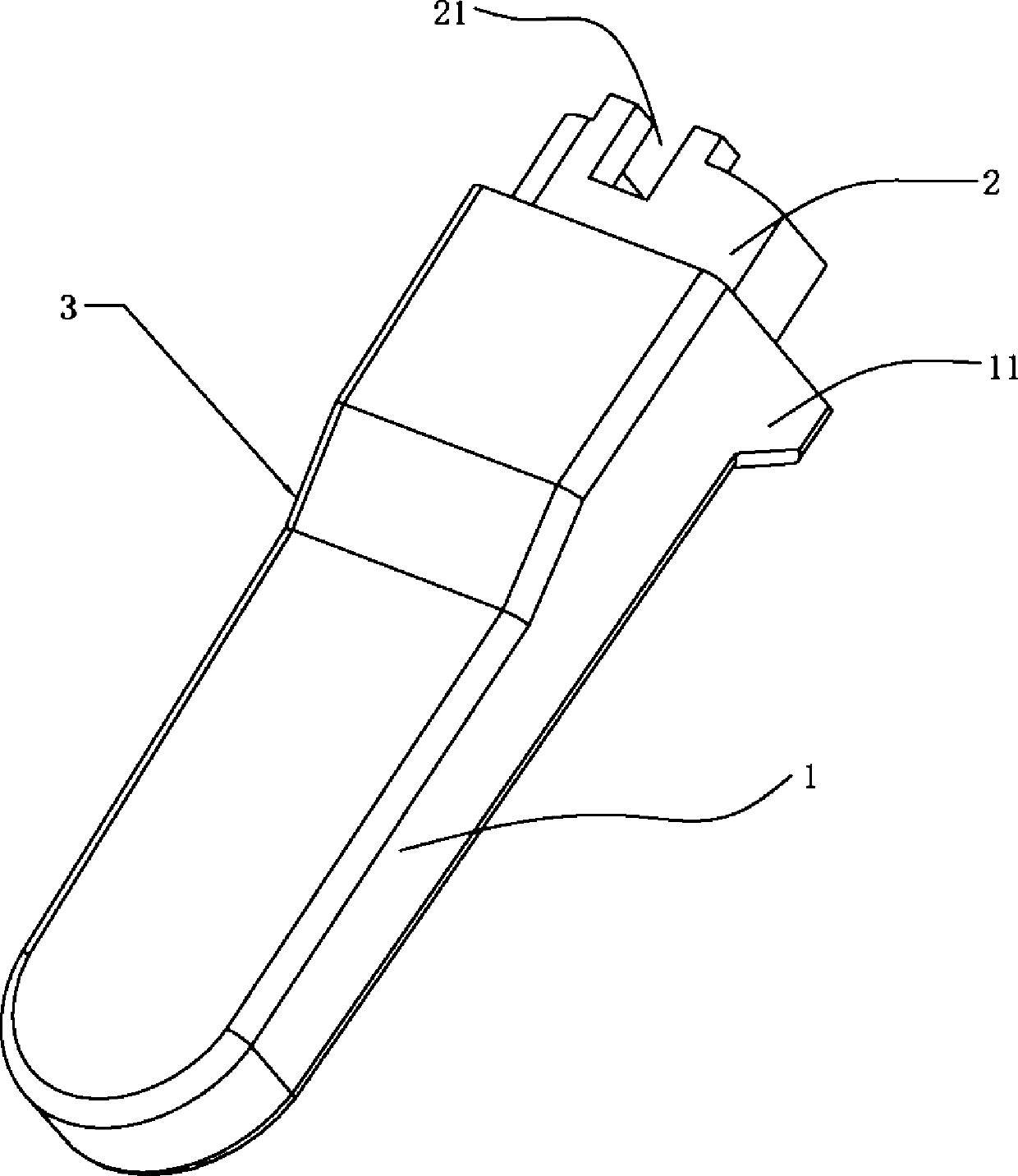
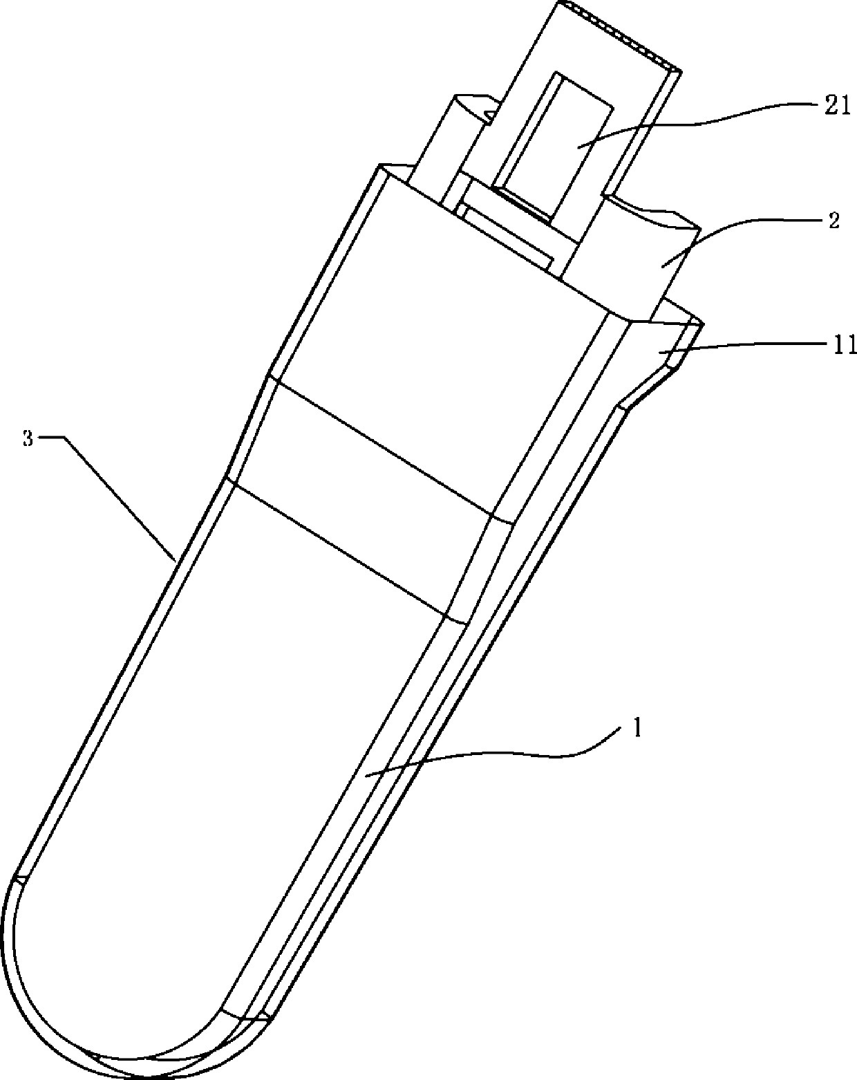
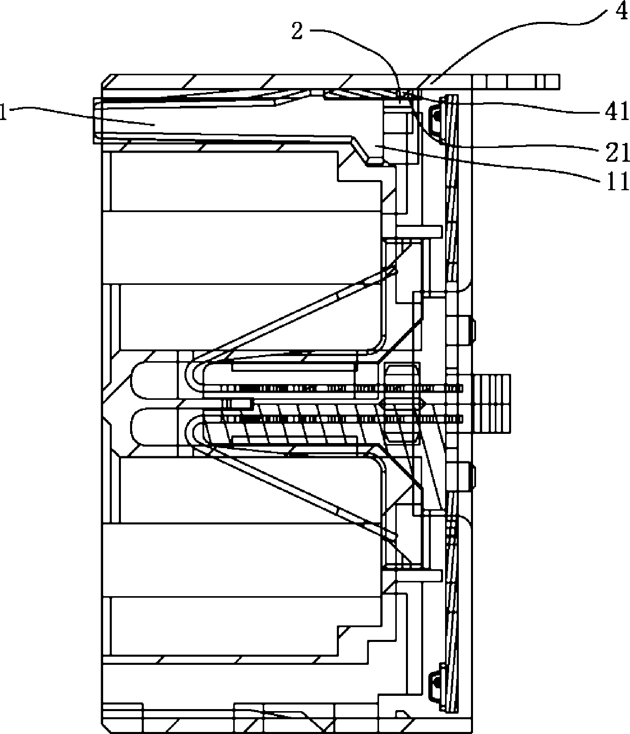
[0039] see Figure 1 to Figure 8 , the present invention will be described in detail below in conjunction with the accompanying drawings.

[0040] A light guide structure according to the present invention includes a bracket, and also includes a light guide body 1, the bracket is a metal bracket 2, and the light guide body 1 is a light guide body 1 made of a high temperature resistant material , the metal bracket 2 is inserted into the colloid forming the light guide body 1 to form a light guide body structure 3 in which the light guide body 1 and the metal bracket 2 are integrated; wherein, the metal bracket 2 is provided at the connection with the connector housing 4 There is a coupling end 21 . In this invention, the inventor changed the PC plastic commonly used in the current light guide body 1 through innovative thinking, and used high temperature resistant materials for the light guide body 1, thereby replacing the PC used in the current light guide body 1. It is made ...


PUM


Abstract

The invention relates to the technical field of LED light guiding bodies, and discloses a light guiding body structure. The light guiding body structure comprises a support and further comprises a light guiding body, the support is a metal support, the light guiding body is made of high-temperature materials, the metal support is inserted into a gel body forming the light guiding body, and the light guiding body structure with the light guiding body and the metal support integrally connected is formed. The invention further discloses a manufacturing method of the light guiding body structure. The manufacturing method comprises the steps of gel preparation, die strip installation, spraying and separation, gel pouring, support inserting, solidification, die separation and shearing. The metal support of the light guiding body structure enables the light guiding body and a connector shell body to be combined conveniently, due to the fact that high temperature resistant materials are adopted by the light guiding body, the phenomenon of fusing deformation cannot occur in the high temperature process that the light guiding body is heated, and therefore the quality of an LED is ensured, and the phenomenon of a dead lamp cannot occur.

Description

technical field [0001] The invention relates to the technical field of LED light guides, in particular to a light guide structure and a manufacturing method thereof. Background technique [0002] At present, in the manufacturing process of the connector, the LED manufacturing process can generally adopt the following two methods: [0003] One is to perform positioning or assembly after bending the LED feet, but due to the suppression of the existing technology, during the bending process of the LED feet, the LED feet will generate stress and transmit it to the inside of the LED body, making Internal components are damaged, resulting in dead lights; the other is to use SMD LEDs with a light guide design. Although this method does not need to bend the LED feet, it needs to go through wave soldering or reflow soldering. The temperature of soldering or reflow soldering is generally between 250° and 260°, while the commonly used light guide material is PC plastic, and its therma...

Claims


Application Information

Patent Timeline
IPC IPC(8): G02B6/00G02B1/04B29C39/02B29C39/22
Inventor 张智凯
Owner DONGGUAN JIAN GUAN PLASTIC ELECTRONICS
Why Eureka
Eureka Blog
Learn More