Light small-size medium-wave infrared continuous zooming imaging lens

An imaging lens, light and small technology, applied in the optical field, can solve the problems that the product cannot achieve the simulated imaging effect, increase the processing difficulty and processing accuracy, reduce the imaging quality of the lens, etc., and achieve good imaging effect, simple structure, and low exercise load. Effect

Active Publication Date: 2013-10-09
BEIJING RES INST OF SPATIAL MECHANICAL & ELECTRICAL TECH
View PDF6 Cites 17 Cited by
  • Summary
  • Abstract
  • Description
  • Claims
  • Application Information

AI Technical Summary

Problems solved by technology

The mid-wave infrared zoom lenses reported above are all designed for large-volume pods, but they cannot meet the requirements of the system with a total length of less than 280mm and a mass of less than 110g. The device is used in a small pod of Φ230mm
In addition, the zoom lenses reported above all use multiple aspherical or diffractive surfaces, which greatly increases the actual processing difficulty and processing accuracy, and the actual processed products cannot achieve the expected analog imaging effect, which undoubtedly greatly reduces the lens image quality

Method used


Image

  • Light small-size medium-wave infrared continuous zooming imaging lens
  • Light small-size medium-wave infrared continuous zooming imaging lens
  • Light small-size medium-wave infrared continuous zooming imaging lens

Examples


Embodiment Construction

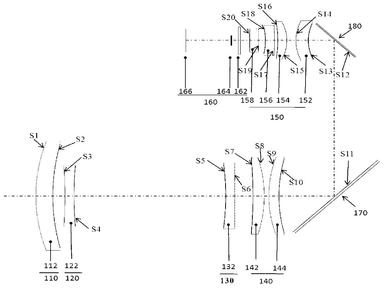
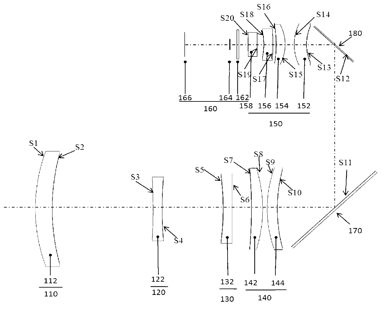
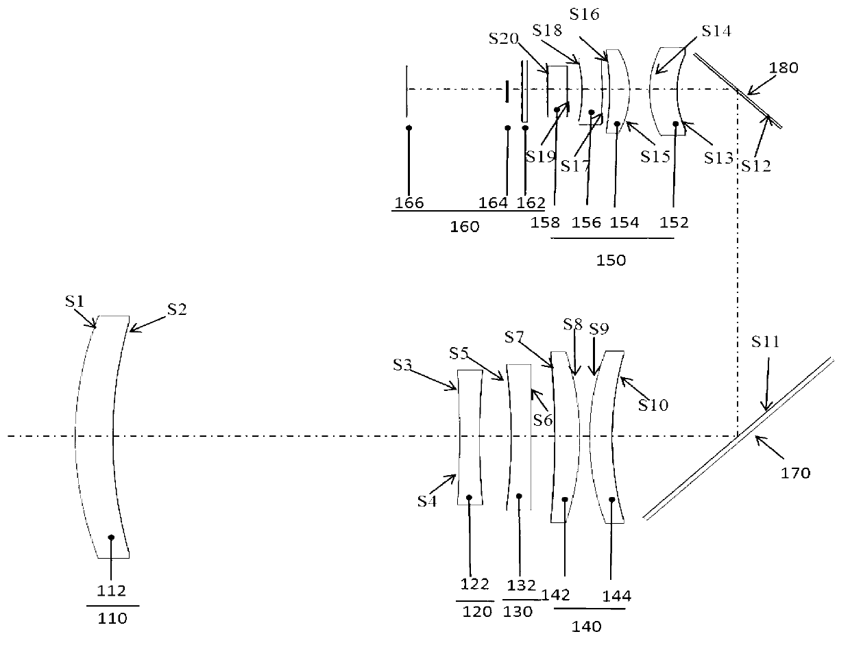
[0021] As shown in Figure 1, the lens of the present invention includes in order from the object side to the imaging side: a first lens group 110 with positive refractive power, a second lens group 120 with negative refractive power, and a third lens with negative refractive power Group 130, a fourth lens group 140 with positive refractive power, a first reflector 170 for refracting the light path, a second reflector 180 for refracting the light path, a fifth lens group 150 with positive refraction, and Detector 160 of the refrigeration unit. in, Figure 1a ~ Figure 1c Corresponding to the three zoom states of telephoto, medium zoom and short zoom respectively. The following are the introductions:

[0022] The first lens group 110 is a front fixed group for converging light beams, including a meniscus silicon positive lens 112 with a convex surface facing the object side.

[0023] The second lens group 120 is a zoom group, which is used to change the focal length of the im...


PUM


Abstract

A light small-size medium-wave infrared continuous zooming imaging lens comprises a first lens set (110), a second lens set (120), a third lens set (130), a fourth lens set (140), a first reflector (170), a second reflector (180), a fifth lens set (150) and a detector (160) from an object space to an imaging space in sequence, wherein the first lens set (110) has positive focal power and is used as a front fixing set, the second lens set (120) has negative focal power and is used as a zooming set, the third lens set (130) has negative focal power and is used as a compensation set, the fourth lens set (140) has positive focal power and is used as a rear fixing set, the first reflector (170) and the second reflector (180) are used for bending a light path, and the fifth lens set (150) has positive focal power. Spherical mirrors are adopted in all the lens, and the light small-size medium-wave infrared continuous zooming imaging lens is simple in structure, small in size, light in weight, and especially suitable for being used in small-size pod equipment.

Description

technical field [0001] The invention belongs to the field of optical technology and relates to an optical imaging lens. Background technique [0002] With the continuous development of precision-guided weapon technology, airborne optoelectronic pods have become an important part of precision strike and tracking systems. The continuous zooming mid-wave infrared system uses photoelectric sensors to realize the continuous zooming process without moving the image plane by moving the lens group, and completes the large field of view search for the target, the fine detailed inspection of the small field of view and the accurate positioning of the target, as well as the target tracking during the zooming process . [0003] The existing mid-wave infrared continuous zoom lens is mainly suitable for relatively large and heavy pods. For example, Yang Weijin and Sun Qiang from the Changchun Institute of Optics, Fine Mechanics and Physics, Chinese Academy of Sciences reported an 18-fol...

Claims


Application Information

Patent Timeline
Patent Type & Authority Applications(China)
IPC IPC(8): G02B15/15
Inventor 葛婧菁秦艳邓德斌纪春梅蔡文娟
Owner BEIJING RES INST OF SPATIAL MECHANICAL & ELECTRICAL TECH
Why Eureka
Try Eureka