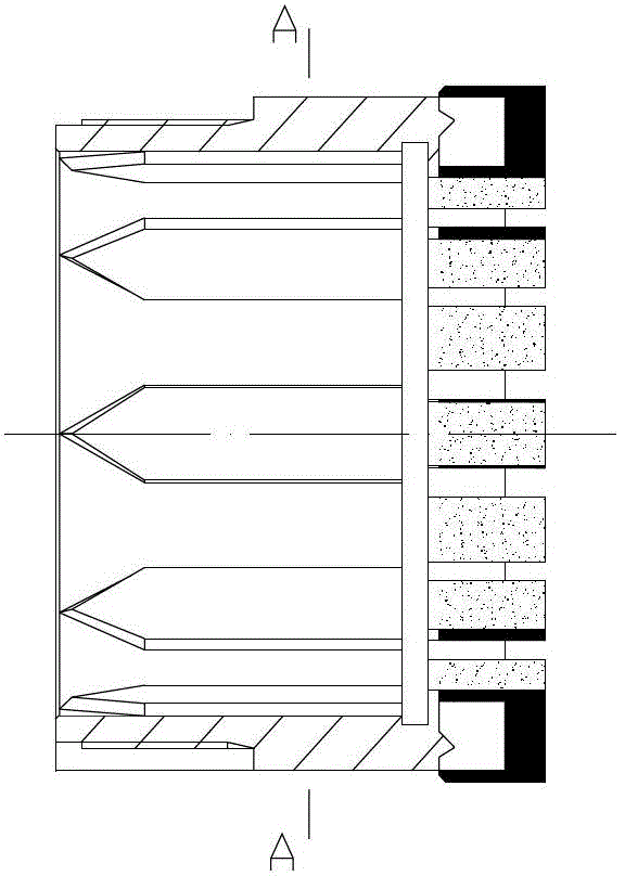
A rope coring drill

A technology of core drilling tools and ropes, which is applied in the direction of extracting undisturbed core devices, earthwork drilling and mining, etc., which can solve the problems of scrapped holes, short drilling intervals, and slow drilling speed of drilling tools, so as to prolong the service life and improve Excellent drilling speed and working conditions

Inactive Publication Date: 2015-12-02
李国民 +1
View PDF13 Cites 0 Cited by
  • Summary
  • Abstract
  • Description
  • Claims
  • Application Information

AI Technical Summary

Problems solved by technology

[0004] However, for conventional wireline core drilling tools, when encountering complex formations such as hard and brittle, soft and hard interbedded, the working environment of the drill bit is very harsh. The advance speed is slow and the drilling interval is short. In addition, because the conventional wireline coring tool lacks a mechanism to protect the core, the broken sample is easy to be eroded and easy to fall off, which reduces the core recovery rate.
It is easy to cause the drilling to be scrapped

Method used


Image

  • A rope coring drill
  • A rope coring drill
  • A rope coring drill

Examples


Embodiment 1

[0032] Please refer to figure 1 The structure on the left side of the drilling tool is shown. This structure provides a core drilling tool for inner drill without lifting the drill bit, retaining spring and core protection rope. Drilling tools are composed of outer pipe assembly and inner pipe assembly.

[0033] The outer pipe assembly comprises the bullet stopper 2, the bullet chamber 4, the outer pipe 11, the reamer 23, the extra joint 16, and the outer drill bit 19, wherein the outer drill bit is an internal spline drill bit with chamfers (such as image 3 , Figure 4 ), the above-mentioned parts are connected with threads in order from top to bottom.

[0034] The inner tube assembly is provided with spear head 1, tension spring 5-1, snap caliper 5-2, recovery tube 3, and clip rack 5-3 from top to bottom. The combination of the above components forms the clip in the inner tube assembly. Mechanism, during installation, first recovery pipe 3 is installed on the bullet fram...

Embodiment 2

[0042] Please refer to figure 1 The structure on the right side of the drilling tool is shown, and this structure provides a split-type stepped drill bit, spring protection, and rope core drilling tool. Drilling tools are divided into outer pipe assembly and inner pipe assembly. The top of the reamer 23 is the same as the cable coring drill of embodiment 1, the bottom of the reamer 23 is connected to the drill seat 21 by a screw, and the inner and outer sides of the lower end of the drill seat 21 are threaded, and the external thread is connected with the outer drill bit 19. The inner thread is connected with the inner drill bit 20 to form the outer pipe assembly of this type of drilling tool structure; the inner pipe assembly is basically the same as the structure in the first embodiment, the difference is that the lower end of the inner pipe 14 is replaced by a retaining spring seat 22 External spline internal drill bit 20 with chamfer, drilling state (such as figure 1 rig...


PUM


Abstract

The invention discloses a rope core taking drill which comprises an outer pipe assembly and an inner pipe assembly. A reamer (23) is arranged in the outer wall assembly, and an inner pipe (14) and a third layer core pipe (15) are arranged in the inner pipe assembly. The rope core taking drill is characterized in that the lower end of the reamer (23) in the outer pipe assembly is connected with an external connector (16), and the lower end of the external connector (16) is connected with an external drill head (19). The lower end of the inner pipe (14) of the inner pipe assembly is connected with an inner drill head (20), and the inner drill head (20) protrudes forwards relative to the external drill head (19). The inner drill head is inserted into the outer drill head in a spline mode, and the inner drill head can be fished out together with the inner pipe, a clamping spring seat (18) and a clamping spring are arranged at the lower portion of the inner side of the third layer core pipe (15), and a blocking spring (17) is arranged on the outer side of the third layer core pipe (15). Regarding complex formation of fracture development, hard brittle fracture, soft and hard interbedding and the like, the drill has the advantages of prolonging the service life to the largest extent, increasing drill lifting intervals, improving the core recovery rate and the like.

Description

technical field [0001] The invention relates to the field of drilling engineering, in particular to a wireline coring tool used in complex formations such as fracture development, hard and brittle, soft and hard interbedded. Background technique [0002] Wireline core drilling tool is a drilling tool that can take out core from the bottom of the hole without lifting the drill bit and drilling tool. It has been widely used in solid mineral core drilling construction at home and abroad. It has long pure drilling time, low labor intensity and high drilling quality. , fewer accidents in the hole, and low drilling costs. [0003] Conventional wireline coring tools are composed of an outer tube assembly and an inner tube assembly, collectively referred to as a double tube. The components include spearhead, spring caliper, inner tube, circlip, adjustment mechanism, suspension mechanism, single-action mechanism, in-position reporting mechanism, core blockage reporting mechanism, et...

Claims


Application Information

Patent Timeline
Patent Type & Authority Patents(China)
IPC IPC(8): E21B25/00
Inventor 李国民钱书伟李锋刘杰周玉瑞张鹏
Owner 李国民
Why Eureka
Try Eureka