Constant-temperature air storage system applied to compressed air energy storage power generation system

A technology for compressed air energy storage and power generation systems, applied in fixed-capacity gas storage tanks, gas/liquid distribution and storage, pressure vessels, etc. Functional capacity and other issues, to achieve the effect of increasing energy storage efficiency, increasing working capacity, and improving energy utilization efficiency

Inactive Publication Date: 2013-10-16
TECHNICAL INST OF PHYSICS & CHEMISTRY - CHINESE ACAD OF SCI
View PDF4 Cites 16 Cited by
  • Summary
  • Abstract
  • Description
  • Claims
  • Application Information

AI Technical Summary

Problems solved by technology

The reduction of the air temperature in the storage tank during the deflation process will bring negative effects in many aspects: First, due to the reduction of the air temperature in the storage tank, the enthalpy of the air decreases, which reduces the work ability of the air, which causes the system The decline of energy storage efficiency; secondly, the reduction of air temperature in the storage tank will cause the safety of the storage tank. In order to achieve the same safety standard, either use materials with lower temperature resistance, or increase the safety factor of the storage tank (such as increase the wall thickness of the storage tank, etc.), resulting in an increase in system cost
[0008] When the gas storage method of underground caves is adopted, although temperature fluctuations will not have an impact on the safety of the gas storage chamber, there is also an impact on the energy storage efficiency of the system due to the increase or decrease of temperature

Method used


Image

  • Constant-temperature air storage system applied to compressed air energy storage power generation system
  • Constant-temperature air storage system applied to compressed air energy storage power generation system

Examples


Embodiment Construction

[0026] The specific implementation of the present invention will be described in further detail below in conjunction with the examples. The following examples are used to illustrate the present invention, but not to limit the scope of the present invention.

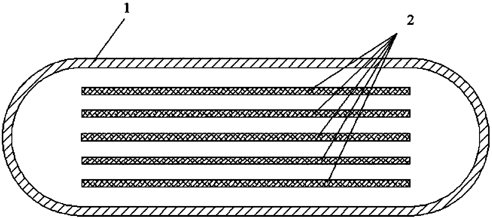
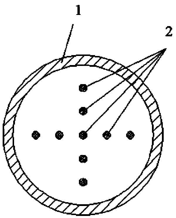
[0027] The constant temperature gas storage system applied to the compressed air energy storage power generation system of the present invention includes a gas storage device 1, which further includes a heat storage device 2 arranged in the gas storage device 1;

[0028] The heat storage device 2 is a phase-change heat storage working medium, or a large specific heat capacity (specific heat capacity greater than 0.5 kJ / kgk) heat storage working medium, or a combination of the two, and is packaged by a packaging structure to form a heat exchange structure.

[0029] The gas storage device 1 of the present invention is used to store high-pressure air of the compressed air energy storage power generation system; the heat storage dev...


PUM


Abstract

The invention relates to the field of compressed air energy storage power generation and particularly relates to a constant-temperature air storage system applied to a compressed air energy storage power generation system. The constant-temperature air storage system comprises an air storage device 1 and a heat storage device 2 arranged in the air storage device, wherein the heat storage device 2 is a heat storage working medium; the required heat storage working medium is a phase change heat storage working medium or the heat storage working medium with the specific heat capacity more than 0.5 kJ / kgk or a combination of the phase change heat storage working medium and the heat storage working medium. The constant-temperature air storage system has the following advantages: firstly, the air storage device can adopt a cheaper steel and iron material, so that the adoption of a more expensive low-temperature-resistant material is avoided and the cost is saved; secondly, heat stored in a high-efficiency heat storage device in an air bleeding process can be used for heating air in the air storage device, so that the primary temperature of the air entering a turbo expander is increased, the work applying capability of the air is improved, and the energy storage efficiency of the system is improved.

Description

Technical field [0001] The present invention relates to the field of compressed air energy storage and power generation. Specifically, the present invention relates to a constant temperature gas storage system applied to a compressed air energy storage and power generation system. Background technique [0002] At present, the biggest problem in electric power science is the engineering storage of electric energy, and it is necessary to find an economically feasible and pollution-free storage technology. In order to solve the problem of large-scale storage of electric energy, countries all over the world have expended huge manpower and financial resources to develop various energy storage methods, such as battery packs, flywheels, super capacitors, superconducting power storage, etc., due to low efficiency and short life. , Inconvenient access, small energy storage capacity, high investment cost, etc., difficult to operate. Compared with other energy storage technologies, compres...

Claims


Application Information

Patent Timeline
Patent Type & Authority Applications(China)
IPC IPC(8): F17C1/00F17C13/00
Inventor 王俊杰薛小代王思贤周远
Owner TECHNICAL INST OF PHYSICS & CHEMISTRY - CHINESE ACAD OF SCI
Why Eureka
Try Eureka