Variable flow resistance

A fluid and flow technology, applied in the field of variable flow resistance, can solve the problems of cooling system operation decline and inability to alleviate

Inactive Publication Date: 2013-10-23
FORD GLOBAL TECH LLC
View PDF6 Cites 9 Cited by
  • Summary
  • Abstract
  • Description
  • Claims
  • Application Information

AI Technical Summary

Problems solved by technology

Failure to relieve such high pressures could result in a degradation of cooling system operation

Method used


Image

  • Variable flow resistance
  • Variable flow resistance
  • Variable flow resistance

Examples


Embodiment Construction

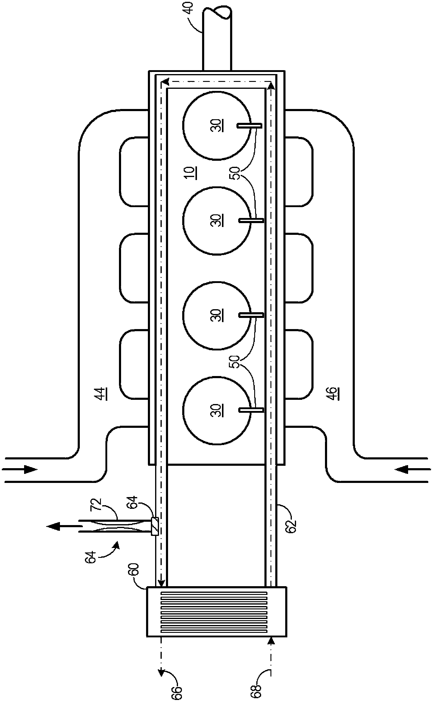
[0015] In internal combustion engines, since the cooling system may exhibit high pressure due to pressurization and high temperature, one or more purge lines may be provided to relieve the pressure in the cooling system. Failure to relieve such high pressures may result in degradation of cooling system operation, for example, because heat removal and distribution may be limited. It may further be desirable to regulate the pressure of gas or other fluid flowing through the purge line. As used herein, "fluid" may equally refer to a substance in either a gaseous or a liquid state.

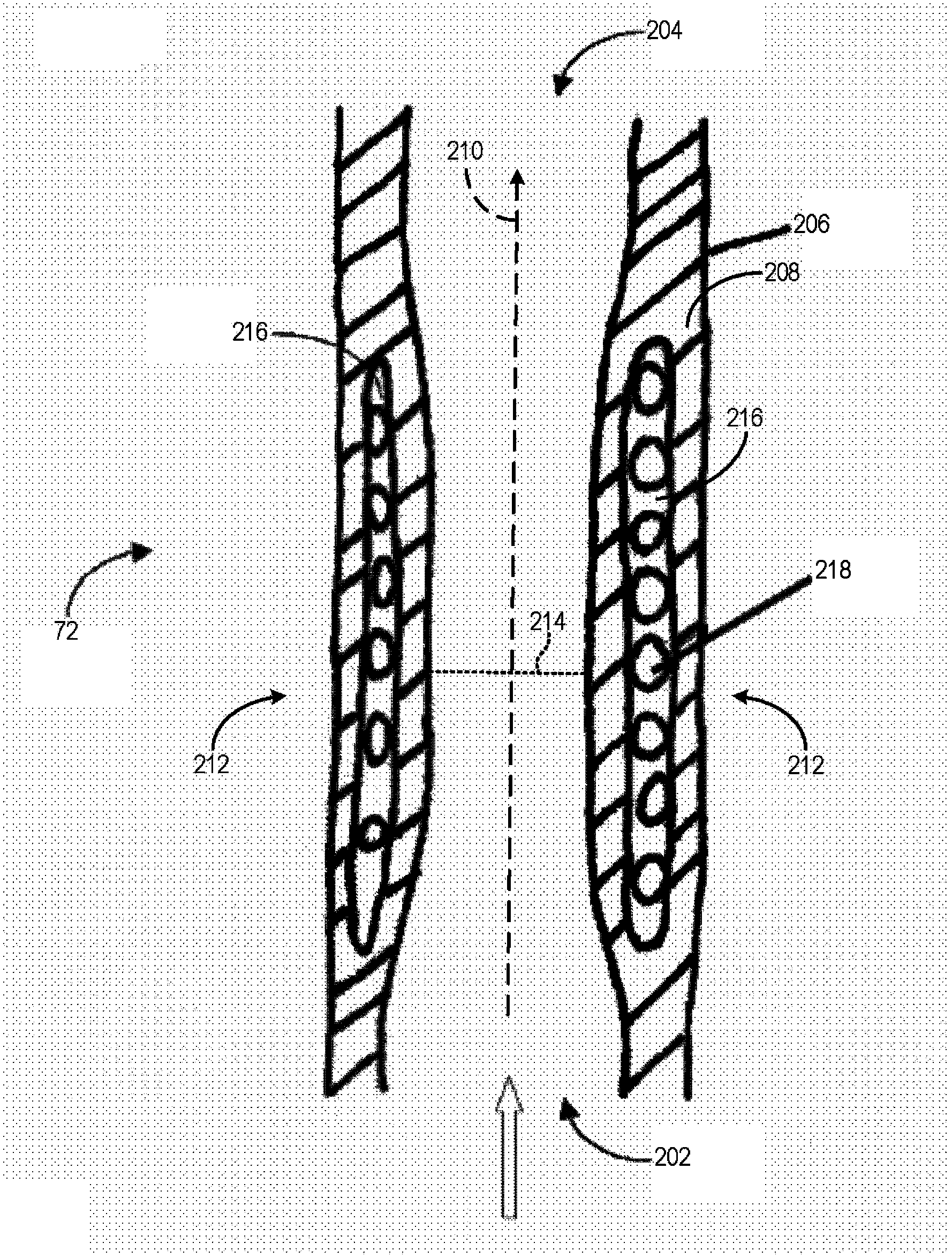
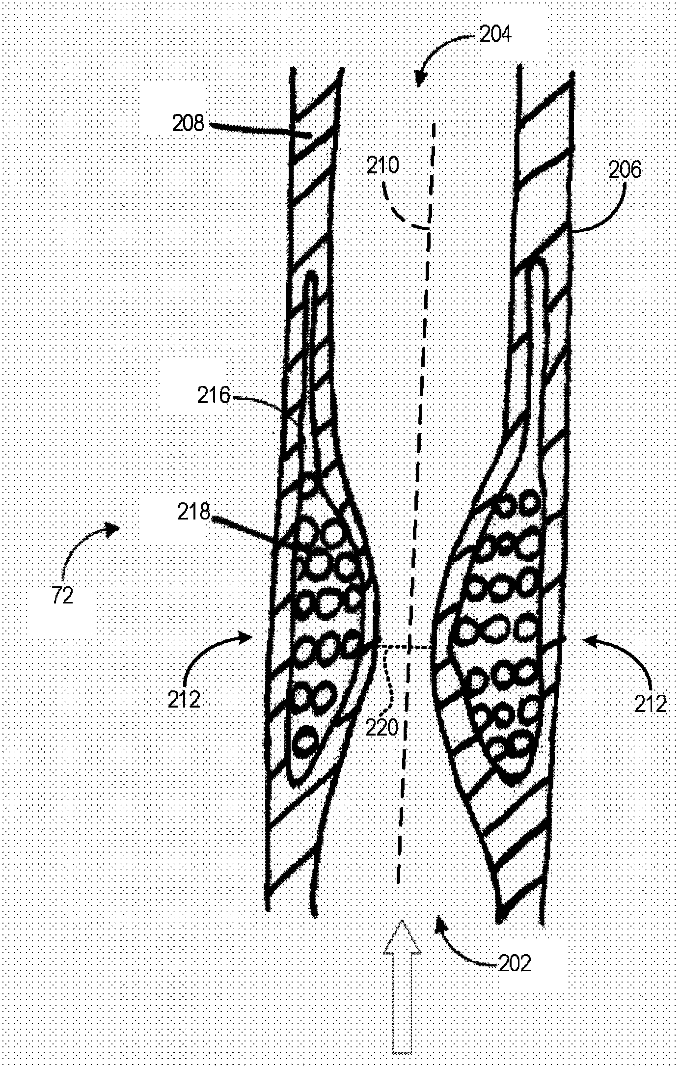
[0016] Various systems are provided for adjusting the flow cross section of fluid flowing through a fluid line. In one embodiment, a system includes a fluid inlet, a fluid outlet, and a hollow body housing forming an elongated hollow body with fluid conduits, the hollow body housing fluidly connecting the fluid inlet to the fluid outlet. The system may further comprise a cross-section control device...


PUM


Abstract

A fluid-carrying conduit achieves variable resistance to flow. An elongate, hollow body casing has at least one chamber containing either a dilatant fluid or an electroactive polymer. In the case of the dilatant fluid, a reduction in an effective flow cross section of the fluid line occurs in reaction to an increase in the shear rate of a fluid flowing through the fluid line. In the case of the electroactive polymer, a reduction in an effective flow cross section of the fluid line occurs in reaction to an electric current being applied to the body casing. The conduit may be configured for use as a degassing line in a cooling system of an internal combustion engine. The conduit may have a reinforcement encircling the electroactive polymer. The conduit may have an electrically conductive connecting surface adjacent to the electroactive polymer. The electroactive polymer may be an ionic electroactive polymer.

Description

[0001] Cross References to Related Applications [0002] This application claims priority from German Patent Application No. 102012205262.3 filed on March 30, 2012, the entire content of which is hereby incorporated by reference for all purposes. technical field [0003] The present disclosure relates to variable flow resistance, and in particular to varying the flow resistance of fluid lines in internal combustion engines. Background technique [0004] In internal combustion engines, since the cooling system may exhibit high pressures due to pressurization and high temperature, one or more purge lines may be provided to relieve the pressure in the cooling system. Failure to relieve such high pressures can result in degradation of cooling system operation. It may further be desirable to regulate the pressure of gas or other fluid flowing through the purge line. [0005] US Patent No. 7,637,892 discloses an implantable variable perfusion pump system having flow resistance o...

Claims


Application Information

Patent Timeline
Patent Type & Authority Applications(China)
IPC IPC(8): F16K7/02F16K31/12
CPCF15C3/04F16L55/02727F15D1/025F16L55/027G05D7/01G05D7/0694F16K7/045Y10T137/2213F16K7/04F16K7/07
Inventor B·布林克曼H·考菲尔德
Owner FORD GLOBAL TECH LLC
Why Eureka
Try Eureka