Solid state laser device array packaging structure and solid state laser device array packaging method

A technology of solid-state lasers and packaging structures, which is applied to laser devices, semiconductor laser devices, lasers, etc., can solve problems such as increasing operational difficulty, high bar laser requirements, and inability to meet array packaging of different power lasers, so as to avoid positive The effect of negative short circuit

Active Publication Date: 2013-10-23
Shandong Huaguang Optoelectronics Co. Ltd.
View PDF8 Cites 12 Cited by
  • Summary
  • Abstract
  • Description
  • Claims
  • Application Information

AI Technical Summary

Problems solved by technology

This packaging structure only provides a packaging structure for high-power lasers, and the cooling heat sink uses industrial water to reduce operating costs, but it cannot meet the needs of different power lasers, and is only suitable for the packaging of devices with consistent bar structures
[0006] To sum up, in the packaging structure of the existing bar laser array, it still only focuses on how to reduce the operating cost of the existing laser, and how to perform uniform optical transformation on the multi-level output light. It is said that the laser arrays in the prior art are only suitable for outputting fixed-power lasers, and cannot meet the requirements for packaging arrays of lasers with different powers
For example, if the existing technology is used to output lasers with different powers, it is necessary to adopt a multi-stage series connection, and the requirements for the subsequent packaging of the bar laser are relatively high: subsequent packaging heat sinks, packaging shells and other packaging materials must be replaced. , not only increases the packaging cost, but also increases the difficulty of operation

Method used


Image

  • Solid state laser device array packaging structure and solid state laser device array packaging method
  • Solid state laser device array packaging structure and solid state laser device array packaging method
  • Solid state laser device array packaging structure and solid state laser device array packaging method

Examples


Embodiment 1

[0036] Embodiment 1 is a solid-state laser array that encapsulates three semiconductor laser bars of different powers, wherein the power and length of the three semiconductor laser bars are shown in Table 1:

[0037] Table 1

[0038] semiconductor laser bar

Embodiment 2

[0039] Embodiment 2 is the packaging method of the packaging structure described in Embodiment 1.

Embodiment 3

[0040] Embodiment 3 is a solid-state laser array that encapsulates three semiconductor laser bars of different powers, wherein the power and length of the three semiconductor laser bars are shown in Table 2:

[0041] Table 2

[0042] semiconductor laser bar

the power

length

first bar

24W

4mm

second bar

54W

9mm

third bar

72W

12mm

[0043] Embodiment 1,

[0044] Such as Figure 2-5 shown.

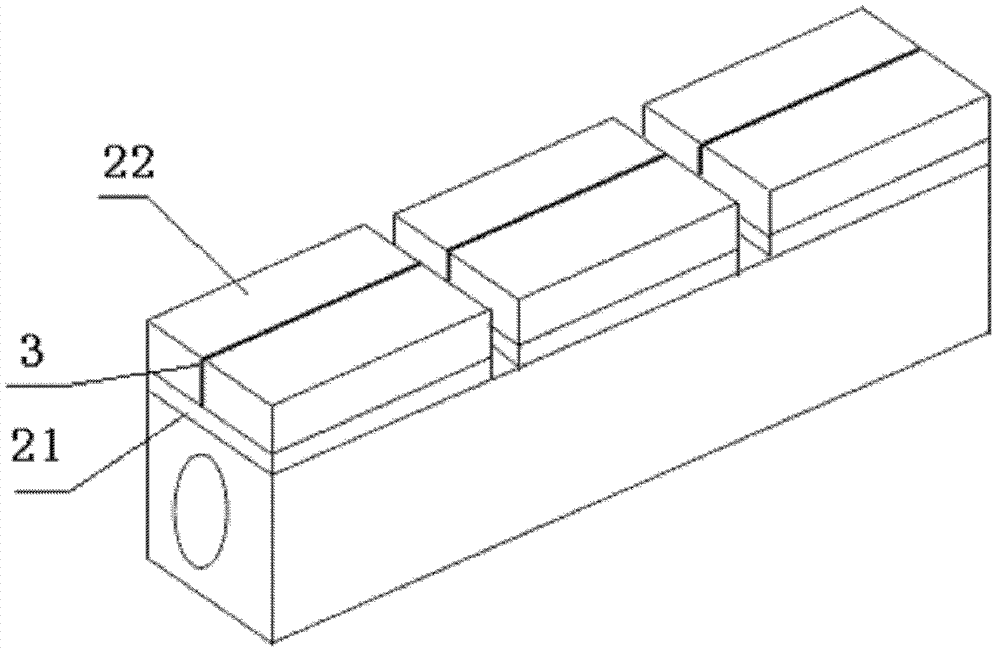
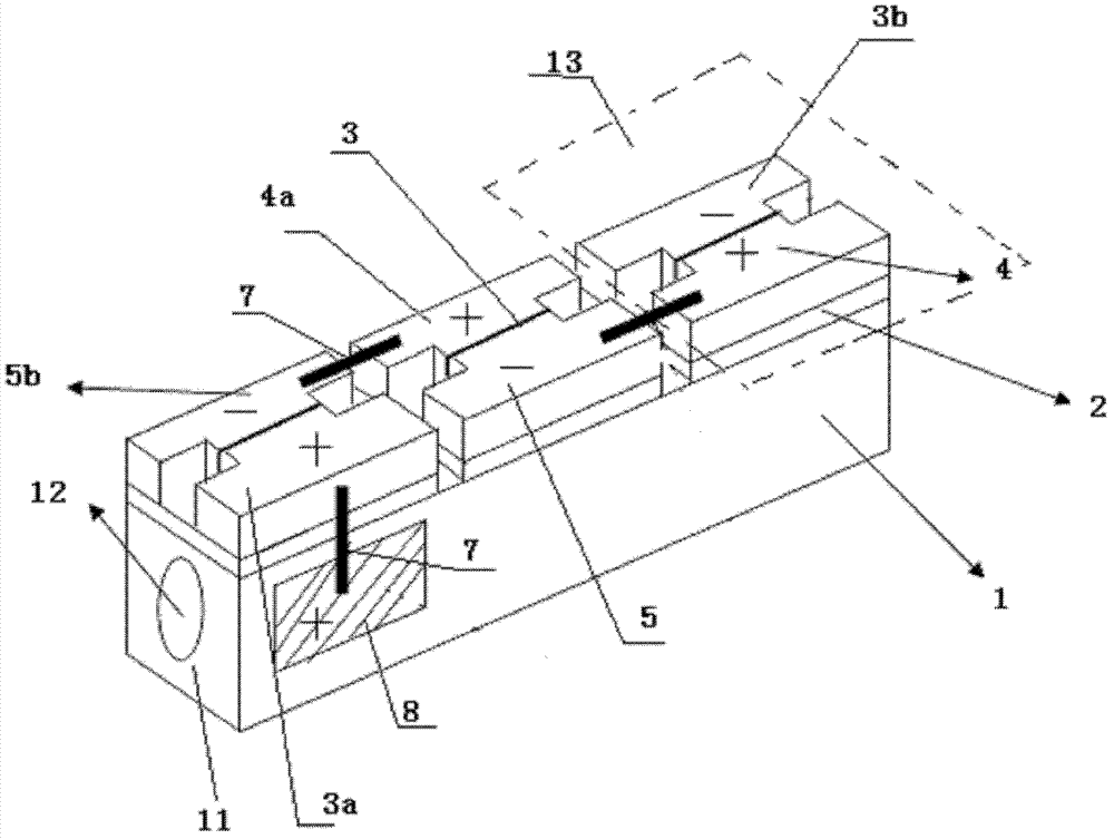
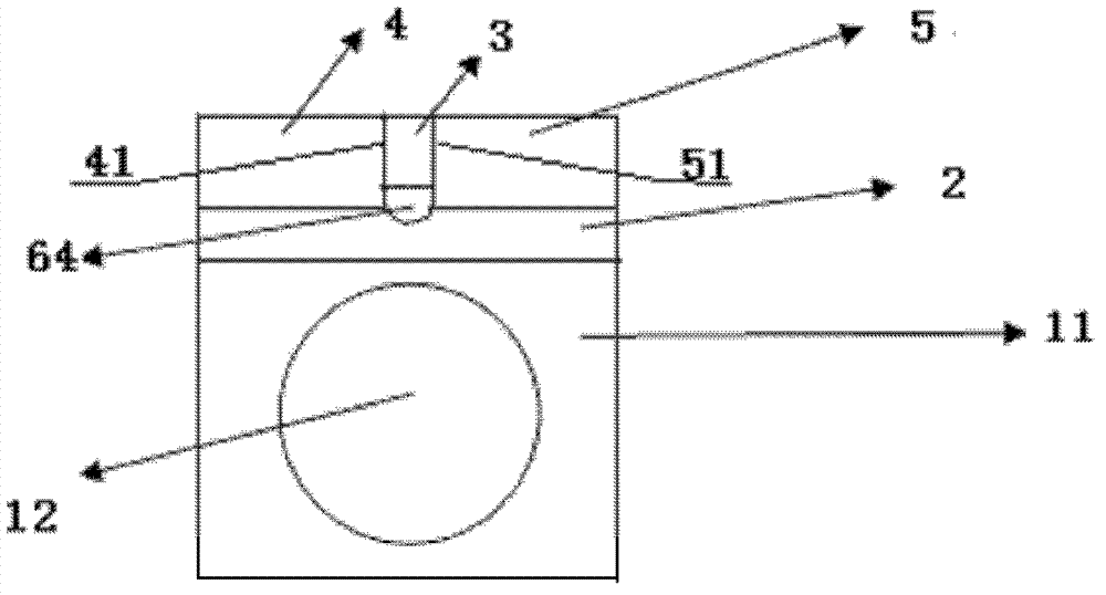
[0045] A packaging structure for a solid-state laser array, including a water-cooling channel 1, an insulating heat-conducting layer 2, a semiconductor laser bar 3, a positive electrode heat sink 4, and a negative electrode heat sink 5; on the water-cooling channel 1, there are three insulating heat-conducting heat sinks arranged at equal intervals Layer 2, a patterned metal layer 6 is provided on the upper surface of each insulating and heat-conducting layer 2, and a metal layer is provided on the lower surface of...


PUM


Abstract

The invention provides a solid state laser device array packaging structure comprising inverse T-shaped positive pole heat sinks and inverse T-shaped negative pole heat sinks, and semiconductor laser device bars are arranged between protruding part end faces of the positive pole heat sinks and protruding part end faces of the negative pole heat sinks. The solid state laser device array packaging structure is characterized in that the positive heat sinks and the negative heat sinks are designed to be of an inverse T-shaped structure; and therefore heat sinks having protruding parts which are different in length can be selected and packaged when six-core, eight-core, ten-core or twenty-core bars are adopted according to the magnitude of power needed by laser devices in packaging processes; different requirements of the laser devices are satisfied, large change of subsequent packaging operation is not needed, and a positive and negative pole short circuit phenomenon which can be easily caused by adoption of rectangular heat sinks can be prevented, and operation difficulty is lowered.

Description

technical field [0001] The invention relates to a packaging structure of a solid-state laser array and a packaging method thereof, belonging to the technical field of solid-state lasers. Background technique [0002] At present, laser diode arrays are widely used in industrial, medical, military and other fields, and the most important application is as a pump source for solid-state lasers. The high-power laser diode array side-pumped solid-state laser can be widely used in laser marking, laser welding, laser cutting, laser drilling, laser medical treatment and laser display. Because semiconductor lasers have the advantages of small size, high power, and stable performance, while lasers are widely used, the performance requirements of lasers are also getting higher and higher. The performance of the laser is not only related to the epitaxial material, but also related to the heat dissipation and packaging of the laser. Due to the different requirements on the power of the l...

Claims


Application Information

Patent Timeline
Patent Type & Authority Applications(China)
IPC IPC(8): H01S5/024H01S5/40
Inventor 王娜张骋李沛旭汤庆敏
Owner Shandong Huaguang Optoelectronics Co. Ltd.
Why Eureka
Try Eureka