
High-frequency transmission line, antenna, and electronic circuit board

A transmission line, high-frequency technology, applied in circuits, printed circuit components, antenna supports/installation devices, etc., can solve the problem of high AC resistance of transmission lines, and achieve the effect of small AC resistance

Active Publication Date: 2013-10-23
TDK CORPARATION
View PDF5 Cites 7 Cited by
  • Summary
  • Abstract
  • Description
  • Claims
  • Application Information

AI Technical Summary

Problems solved by technology

Also, as the frequency of the AC signal becomes higher, the current concentrates on the surface of the transmission line, so the AC resistance of the transmission line becomes higher

Method used


Image

  • High-frequency transmission line, antenna, and electronic circuit board
  • High-frequency transmission line, antenna, and electronic circuit board
  • High-frequency transmission line, antenna, and electronic circuit board

Examples


Embodiment

[0055] Hereinafter, the contents of the present invention will be described in more detail using examples and comparative examples, but the present invention is not limited to the following examples.

[0056] [Sample 1]

[0057] (Step of forming conductor layer 6 )

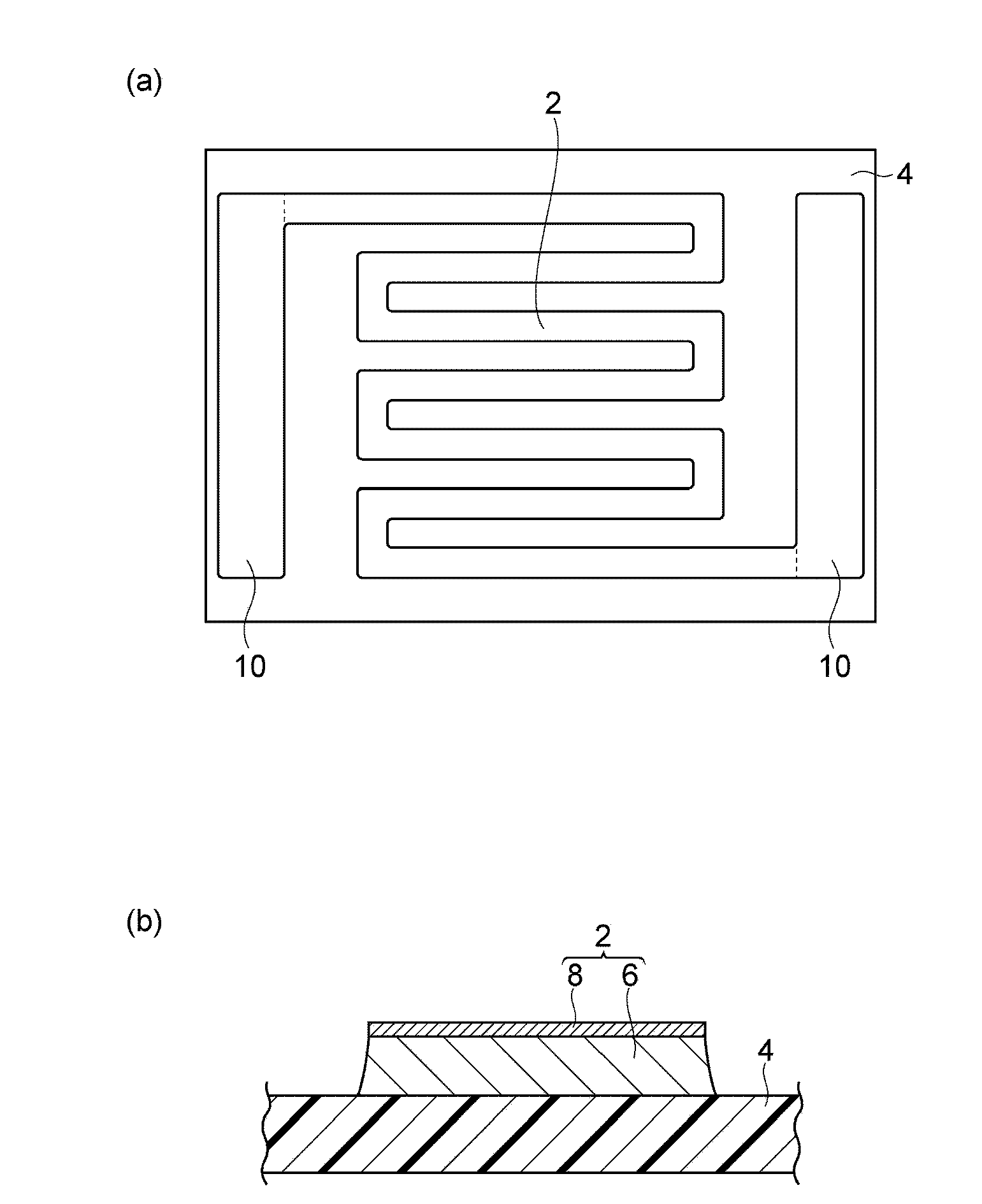
[0058] A resist was applied to the entire surface of the copper foil laminated on the glass epoxy substrate by a known method. Then, exposure of the zigzag pattern, development, copper etching, and etchant stripping are performed. Through these series of steps, a zigzag pattern (conductor layer 6) made of copper and measurement terminals connected to both ends thereof are formed along the surface of the glass epoxy resin substrate (insulating base 4) (see figure 1 a. figure 1 b. ). The dimensions of the glass epoxy substrate were 4.5 mm in width x 3.2 mm in length x 0.8 mm in thickness. The line width of the zigzag pattern was 200 μm. The line length of the zigzag pattern is 19.7 mm. The area S of the zigz...


PUM

PropertyMeasurementUnit
Thicknessaaaaaaaaaa
Arithmetic mean roughnessaaaaaaaaaa
Ten point average roughnessaaaaaaaaaa

Abstract

A high-frequency transmission line having low alternate current (AC) resistance is provided. One aspect of the present invention is a high-frequency transmission line disposed along a surface of an insulating support, wherein, letting F [Hz] be the frequency of an AC electric signal transmitted by the high-frequency transmission line and Ms [Wb / m] be the saturation magnetization per unit area, the frequency value F and the saturation magnification value per unit area Ms satisfy the following expression (1): Ms@(1.5×10²) / F+5.7×10⁻⁸.(1)

Description

technical field [0001] The present invention relates to a high frequency transmission line, antenna (radiating conductor and absorbing conductor) and electronic circuit substrate. Background technique [0002] In electronic components, transmission lines for transmitting electrical signals are provided. To welcome the advent of the highly information age in recent years, the frequency band of the AC signal transmitted by the transmission line is shifting to the high frequency band. For example, the communication frequency band of mobile information terminals reaches hundreds of [MHz] to several [GHz]. A skin effect occurs in a high-frequency transmission line that transmits such an AC signal in a high-frequency range. Due to the skin effect, when a high-frequency electrical signal flows in the transmission line, the current density becomes higher on the surface of the transmission line, and becomes lower as it moves away from the surface. Furthermore, as the frequency of ...

Claims


Application Information

Patent Timeline
IPC IPC(8): H05K1/09H01Q1/38H01Q1/22
CPCH01P3/08H01P11/003H01Q1/50H01Q1/36
Inventor 吉田健一堀川雄平
Owner TDK CORPARATION
Learn More