
crankcase and internal combustion engine

A technology for crankcases and internal combustion engines, applied in the field of crankcases, can solve problems such as pollution

Active Publication Date: 2016-06-15
ROLLS ROYCE SOLUTIONS GMBH
View PDF7 Cites 0 Cited by
  • Summary
  • Abstract
  • Description
  • Claims
  • Application Information

AI Technical Summary

Problems solved by technology

However, it is problematic here that, as already mentioned, the oily component of the leaking gas contaminates subsequent ventilators, compressors and other guiding and conveying elements of the forced circulation circuit

Method used


Image

  • crankcase and internal combustion engine
  • crankcase and internal combustion engine
  • crankcase and internal combustion engine

Examples


Embodiment Construction

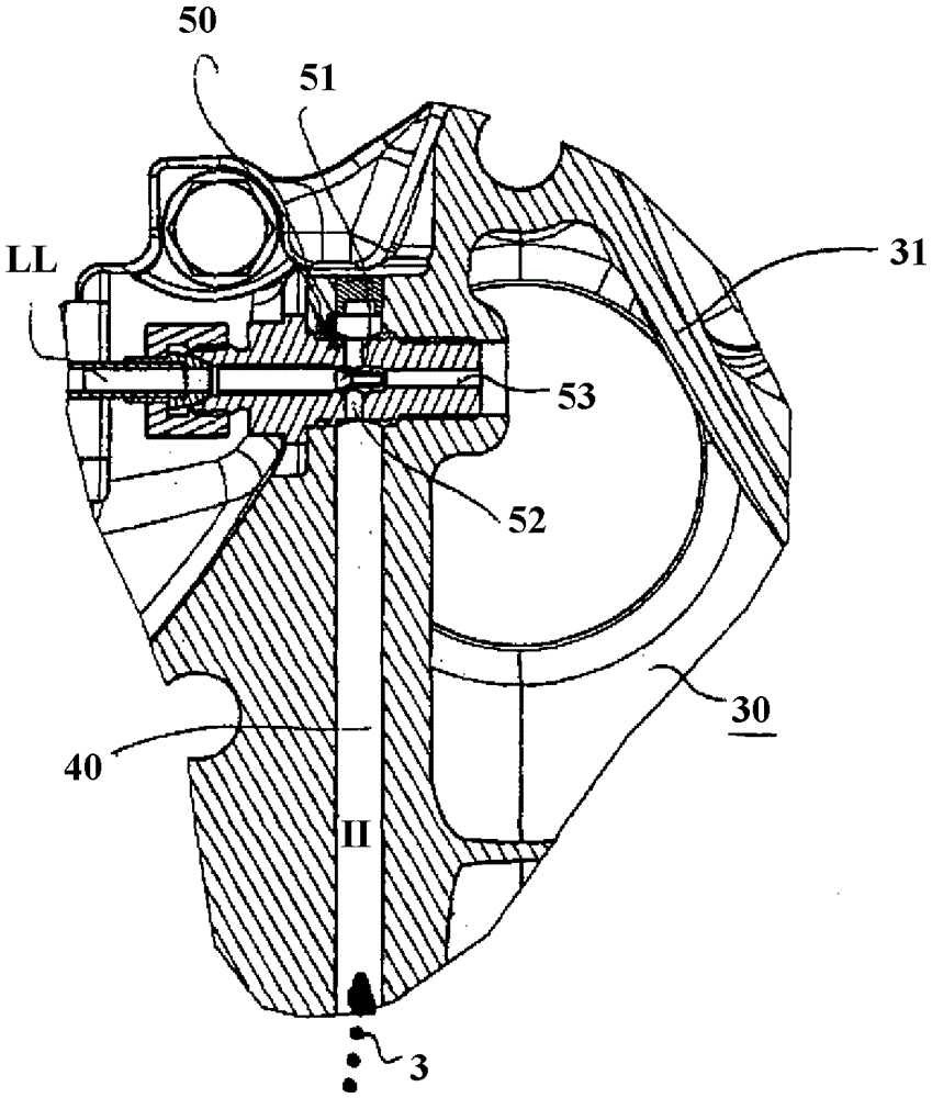
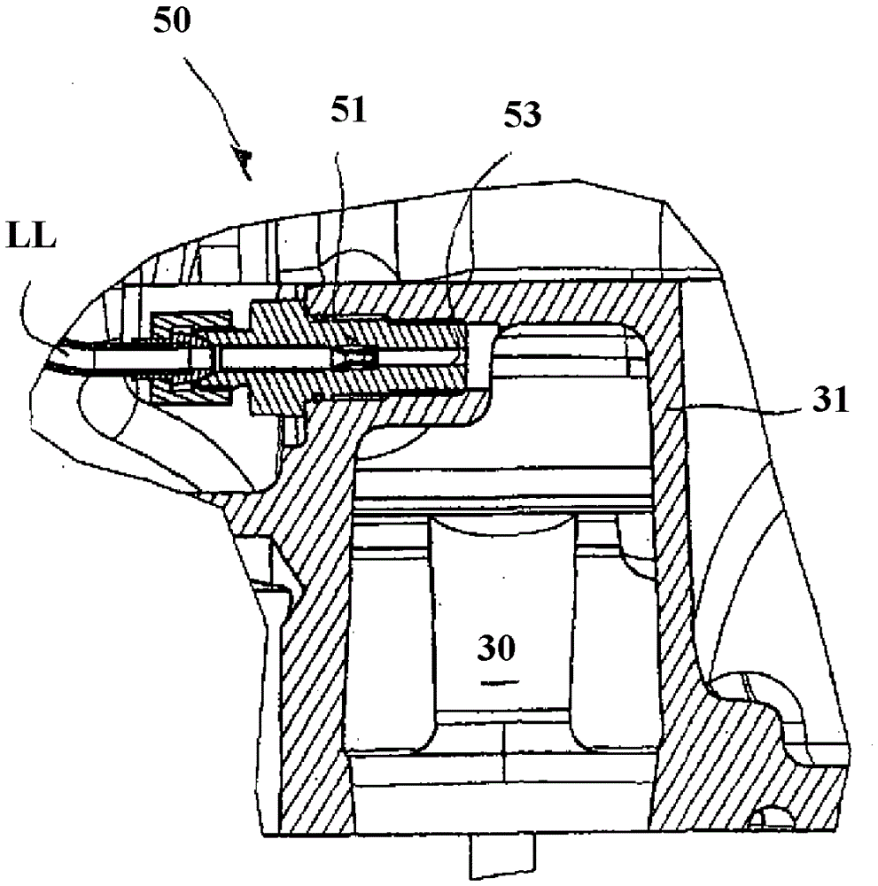
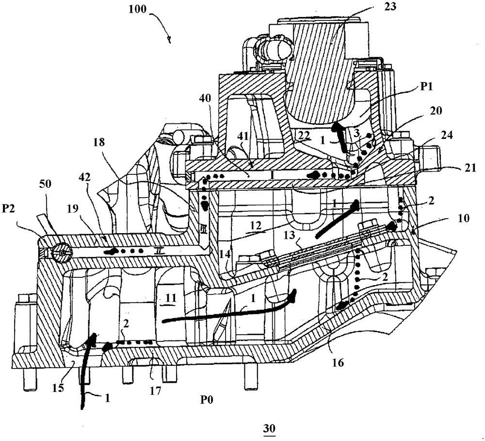
[0032] figure 1 A crankcase 100 for an internal combustion engine, not shown in detail, is shown. Presently, the upper part of a crankcase 100 is shown with the ventilation housing part 10 and the carrier housing part 20 arranged thereon. The crank chamber 30 of the crankcase 100 is located below the ventilation housing part 10 , in which the cylinder head, the crankshaft and finally also the oil sump are arranged one above the other. Blow-by gas 1 mixed with oil is conducted here from crankshaft chamber 30 via one or more channels to almost the highest point of crankcase 100 . In principle, such channels, not shown in detail here, can be integrated not only in the crankcase casting, but also as external channels (such as hoses or lines, etc.). The leakage gas 1 is introduced into the ventilation housing part via the opening 15 , which is largely protected from spray oil. A further embodiment of both the ventilation housing part 10 and the carrier housing part 20 serves to ...


PUM


Abstract

A crankcase (110) for an internal combustion engine, with a suction device associated with the crankcase (100), which is designed for the crankcase (100) to respond to leakage gases (1), in particular gas-oil mixtures ventilation to generate a limited negative pressure (P1, P2) in the crankcase (100); and with at least one separating wall (14) configured for the delivery of leakage gases (1) and the removal of oil (3) separation. According to the invention, a ventilation housing part ( 10 ) and a carrier housing part ( 20 ) arranged thereon are provided, wherein a separating wall is formed between the ventilation housing part ( 10 ) and the carrier housing part ( 20 ) And the suction means are formed in the form of a suction jet pump (50), which is configured to suction the oil (3) from the separation wall (14).

Description

technical field [0001] The invention relates to a crankcase for an internal combustion engine with a suction device associated with the crankcase, which is designed for the blow-by-gas, in particular gas-oil, of the crankcase ventilation of the mixture to create a restricted negative pressure in the crankcase; and with at least one separating wall configured for delivery of blow-by gases and separation of oil. Background technique [0002] Problems due to leakage gases mixed with oil in the crankcase are known, for example, from document DE234479. It is basically unavoidable in internal combustion engines that a certain amount of fuel gas is squeezed into the interior of the crankcase in a mixed manner with oil or volatile components of the oil between the working piston and the combustion cylinder. In the mentioned document it is proposed to suck up the corresponding leakage gas via a ventilator to avoid the deposition of oil components in the ventilator or subsequent pipe...

Claims


Application Information

Patent Timeline
Patent Type & Authority Patents(China)
IPC IPC(8): F01M13/04
CPCF01M13/0405F01M2013/0072F01M2013/0427F01M2013/0433F01M2013/0438F01M2013/0461F01M2013/0488F01M11/00
Inventor M.施泰特J.W.豪斯克内希特R.格贝特
Owner ROLLS ROYCE SOLUTIONS GMBH
Learn More