
Spraying powder booth for surfaces of metal parts

A technology of surface spraying and powder spraying room, which is applied to the surface coating liquid device, coating, spraying device, etc. It can solve the problems of wasting plastic powder, affecting work efficiency, and not being able to adapt to the spraying of special-shaped workpieces. Small loss, the effect of improving work efficiency

Inactive Publication Date: 2013-10-30
DEYANG HENGDA LUMINAIRE MFG
View PDF0 Cites 2 Cited by
  • Summary
  • Abstract
  • Description
  • Claims
  • Application Information

AI Technical Summary

Problems solved by technology

The powder spraying room of this structure has the following disadvantages: First, because the existing powder spraying room door is generally a whole, it cannot adapt to the spraying operation of special-shaped workpieces.
When the workpiece is lifted by a spreader, although the lifting rope of the spreader is thinner, the width of the door needs to be opened narrower, and the workpiece is often thicker, and the width of the door needs to be opened wider. Open the door of the thickness of the workpiece, which leads to the wide opening of the powder spraying room door as a whole, so that a large amount of dust in the powder spraying room is scattered into the air outside the powder spraying room, resulting in plastic powder waste and air pollution; second, the current plastic powder room is generally Using multi-level powder recycling, when multi-color powder spraying operations are required, it will be very difficult to change powder, which affects work efficiency and wastes plastic powder

Method used


Image

  • Spraying powder booth for surfaces of metal parts
  • Spraying powder booth for surfaces of metal parts
  • Spraying powder booth for surfaces of metal parts

Examples


Embodiment Construction

[0020] All features disclosed in this specification, or steps in all methods or processes disclosed, may be combined in any manner, except for mutually exclusive features and / or steps.

[0021] Any feature disclosed in this specification (including any appended claims, abstract and drawings), unless expressly stated otherwise, may be replaced by alternative features which are equivalent or serve a similar purpose. That is, unless expressly stated otherwise, each feature is one example only of a series of equivalent or similar features.

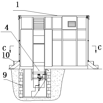
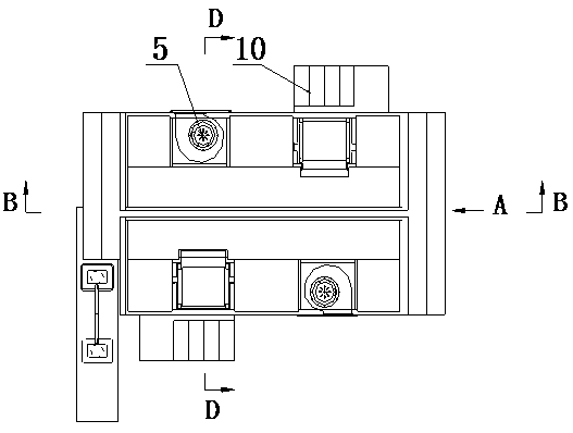
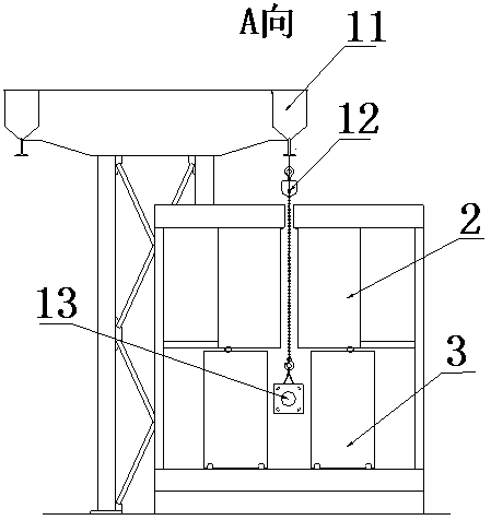
[0022] Such as Figures 1 to 6 As shown, a metal parts surface spraying powder spraying room includes a powder spraying room body 1, a working platform 4 in the powder spraying room body 1 and a powder spraying room door, and the powder spraying room door includes an upper door group 2 and a lower door group 3. The upper door group 2 and the lower door group 3 are respectively composed of a number of independently opened and closed doors; a p...


PUM


Abstract

The invention discloses a spraying powder booth for surfaces of metal parts. The spraying powder booth comprises a powder booth body, a working platform and powder booth doors. The working platform is arranged in the powder booth body, the powder booth doors include an upper door group and a lower door group, each of the upper door group and the lower door group comprises a plurality of door parts capable of being independently opened, a molding powder recycling system is arranged at a position directly facing the working platform and comprises molding powder recycling fans, molding powder recycling filter elements, air pipes and a molding power recycling groove, the molding powder recycling filter elements directly face the molding powder recycling fans, each air pipe is positioned inside the corresponding molding powder recycling filter element and is connected with an electromagnetic pulse valve, and the molding powder recycling groove is positioned on the oblique lower sides of the molding powder recycling filter elements. The spraying powder booth has the advantages that loss of molding powder can be effectively reduced, a healthful working environment can be provided for operators, and the work efficiency can be greatly improved.

Description

technical field [0001] The invention relates to a spraying operation device, in particular to a lifting type powder spraying booth. Background technique [0002] When making large metal parts, especially for outdoor metal parts, it is often necessary to spray the surface of large metal parts for anti-corrosion and other needs. Since the spraying powder will spread everywhere during the spraying operation, in order to save plastic powder and meet the needs of environmental protection, the spraying operation is often carried out in a closed powder spraying room. [0003] At present, the common structure of the powder spraying room generally includes the powder spraying room body and the powder recovery device, and the workpiece is transported from the powder spraying room to the powder spraying room through the hanger and the spreader group. The powder spraying booth of this structure has following shortcoming: the one, because the existing powder spraying booth door is gener...

Claims


Application Information

Patent Timeline
IPC IPC(8): B05B15/12B05B15/04
CPCY02P70/10
Inventor 代明生
Owner DEYANG HENGDA LUMINAIRE MFG
Learn More