Substrate processing equipment

A substrate processing device and substrate technology, which are applied in gaseous chemical plating, metal material coating process, coating, etc., can solve problems such as reduced productivity

Active Publication Date: 2016-08-03
TOKYO ELECTRON LTD
View PDF6 Cites 0 Cited by
  • Summary
  • Abstract
  • Description
  • Claims
  • Application Information

AI Technical Summary

Problems solved by technology

[0007] On the other hand, for the above-mentioned normal temperature wafers and wafers that have been heat-treated in advance, before the temperature of the wafers is to be made uniform in the entire surface, that is, before the wafers become flat, the wafers are kept on standby, for example, above the turntable. When the position is slightly separated from the turntable on the side, the productivity will decrease by the amount corresponding to the time for which the wafer is placed on standby in advance.

Method used


Image

  • Substrate processing equipment
  • Substrate processing equipment
  • Substrate processing equipment

Examples


Embodiment

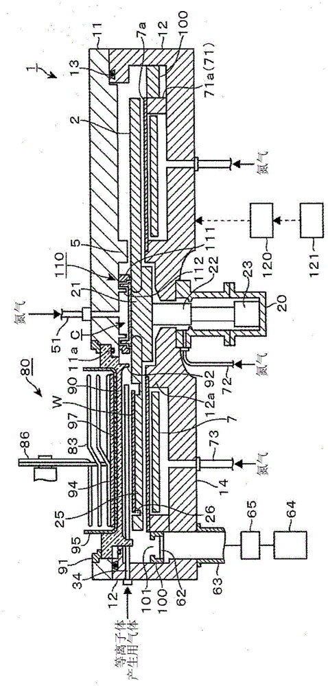
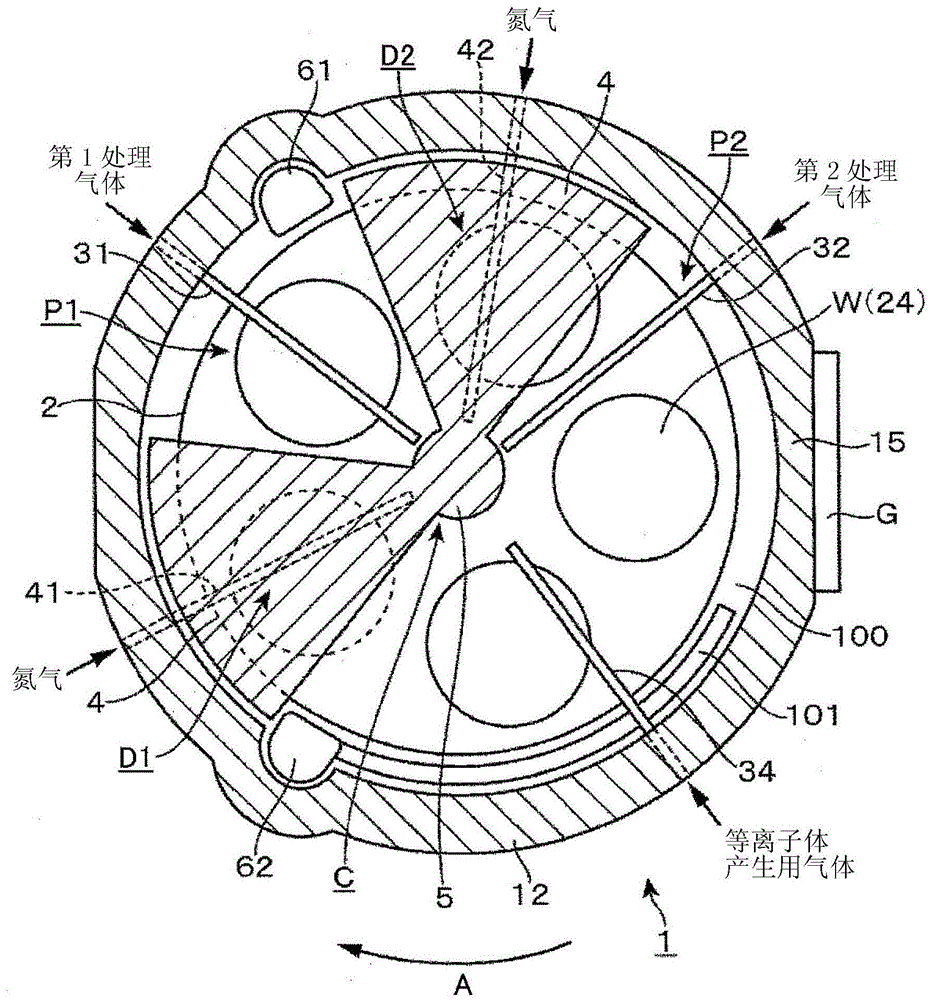
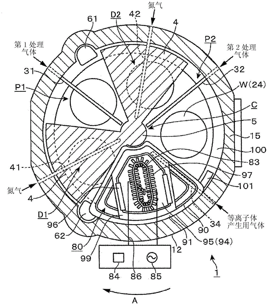
[0105] use the above figure 1 The substrate processing device was used to perform film formation on five wafers 1 to 5, and the results are shown in the following Table 2 and Figure 23 As shown in FIG. 2 , there were very few particles adhering to the surfaces of the aforementioned wafers 1 to 5 .

[0106] Table 2: Examples

[0107]

Wafer 1

Wafer 2

Wafer 3

Wafer 4

Wafer 5

0.10μm~0.16μm

13

15

16

15

27

0.16μm~0.30μm

7

21

12

10

9

0.30μm~0.70μm

0

9

3

7

1

0.70μm~3.00μm

0

0

0

0

0

3.00μm~

0

0

0

0

0

total

20

45

31

32

37

average

31

[0108] On the other hand, using the above Figure 7 and Figure 8 The same treatment was carried out on the rotary table 2 described (comparative example 1), and the results are shown in Table 3 and Figure 24 As...


PUM


Abstract

A substrate processing apparatus includes a vacuum chamber; a turntable rotatably provided in the vacuum chamber, on which a circular substrate is to be mounted, and provided with a circular concave portion at a front surface having a larger diameter than that of the substrate, and a circular substrate mounting portion provided in the concave portion having a diameter smaller than that of the concave portion and the substrate at a position higher than a bottom portion of the concave portion, the center of the substrate mounting portion being off center with respect to the center of the concave portion toward an outer peripheral portion side of the turntable; a process gas supplying unit which supplies a process gas to the substrate; and a vacuum evacuation mechanism which evacuates the vacuum chamber.

Description

technical field [0001] The present invention relates to a substrate processing apparatus for processing a substrate with a processing gas. Background technique [0002] As a substrate such as a semiconductor wafer (hereinafter referred to as "wafer"), for example, a silicon oxide film (SiO 2 ) and other thin films, for example, the Atomic Layer Deposition (ALD) method using the apparatus described in Patent Document 1 is known. In this device, five wafers are arranged in the circumferential direction on a turntable, and a plurality of gas nozzles are arranged on the upper side of the turntable, so that various reactions that react with each other are sequentially supplied to each rotating wafer. gas. Recesses are arranged on the turntable for receiving and holding individual wafers. The concave portion is formed to be slightly larger than the wafer in plan view in order to detachably hold the wafer so that a gap is provided between the concave portion and the outer edge o...

Claims


Application Information

Patent Timeline
Patent Type & Authority Patents(China)
IPC IPC(8): C23C16/455
CPCC23C16/4584C23C16/4401C23C16/46
Inventor 加藤寿菱谷克幸
Owner TOKYO ELECTRON LTD
Why Eureka
Try Eureka