Commercial gas stove waste heat utilization device

A technology of gas stoves and waste heat, which is applied in household stoves, household heating, household heating, etc., can solve the problems of poor working environment for chefs, high air temperature in kitchens, energy waste, etc., and achieve reduced energy consumption and high heat utilization efficiency , the effect of improving thermal efficiency

Inactive Publication Date: 2013-10-30
金元革
View PDF0 Cites 5 Cited by
  • Summary
  • Abstract
  • Description
  • Claims
  • Application Information

AI Technical Summary

Problems solved by technology

[0002] At present, most of the existing commercial gas stoves have a hearth made of solid materials such as refractory bricks or heat-resistant cast iron. The heat generated by gas combustion is not only partially absorbed by the bottom of the pot for cooking, but also partly absorbed by the hearth. Distributed into the kitchen air; such a large amount of waste heat is directly dissipated into the kitchen air, which not only causes a great waste of energy, but also makes the kitchen air temperature higher, and the chef's working environment is poor

Method used


Image

  • Commercial gas stove waste heat utilization device

Examples


Embodiment

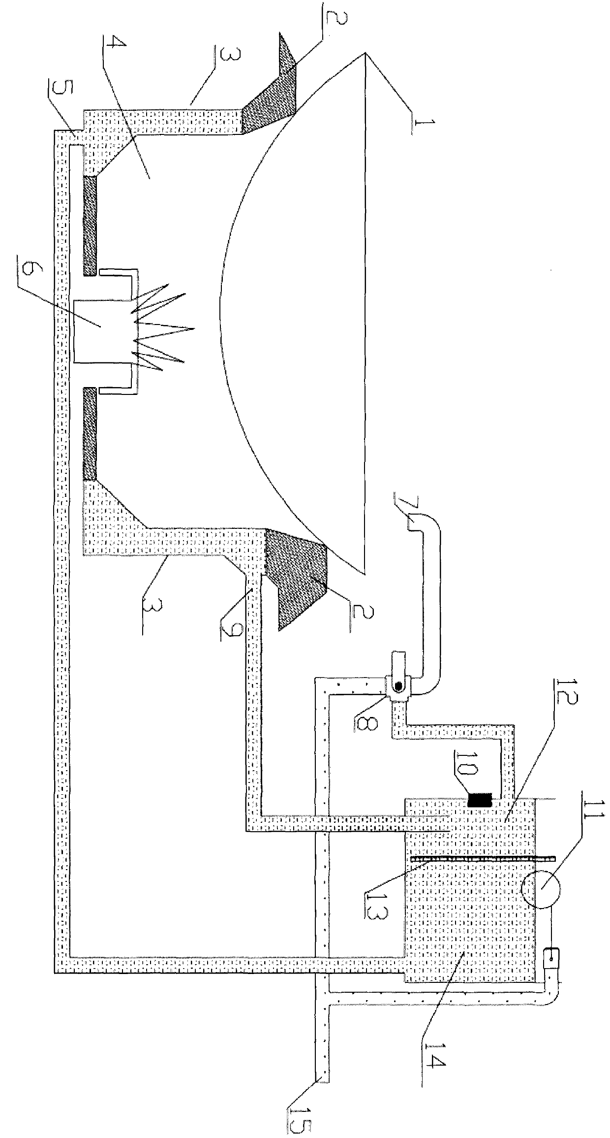
[0014] Such as figure 1 As shown, a commercial gas stove waste heat utilization device of the present invention is composed of a pot 1, a fort pan frame 2, a water jacket furnace 3, a combustion chamber 4, a furnace water inlet 5, a flame outlet 6, a water outlet 7, a water outlet switch 8, Furnace hearth water outlet 9, water temperature sensing alarm device 10, float valve 11, hot water tank 12, heat insulation baffle 13, cold water tank 14 and cold water inlet 15 are formed. Cold water enters the waste heat utilization device of the present invention through the cold water inlet 15, and enters the cold water tank 14 through the ball float valve 11; the furnace water inlet 5 is at the bottom of the water jacket furnace 3, and the furnace water outlet 9 is at the top of the water jacket furnace 3; The water inlet 5 is connected to the cold water tank 14, the furnace outlet 9 is connected to the hot water tank 12, the hot water tank is separated from the upper part of the cold...


PUM


Abstract

The invention relates to a commercial gas stove waste heat utilization device which is composed of a water-jacket-type hearth, a water storage box, a hearth water inlet pipe, a hearth water outlet pipe, a water outlet valve, a ball float valve and a cold water inlet, wherein the partial waste heat which is not utilized by the cooking among the heat generated by gas combustion is absorbed by water in a hearth through the water-jacket-type hearth; after the water is heated in the hearth, the water automatically flows from the hearth water inlet pipe into the hearth water outlet pipe; the hearth water outlet pipe is connected with a hot water box; the hearth water inlet pipe is communicated with a cold water box; the upper parts of the hot water box and the cold water box are separated by a thermal-insulation baffle plate; the bottoms of the hot water box and the cold water box are communicated. Thus, under the flowing of the water in the hearth, the water in the cold water box is driven to flow into the hearth, so that the water in the hearth flows into the hot water box; the relatively cold water at the bottom of the hot water box flows into the cold water box. Therefore, the water in water boxes is heated circularly. As a result, the heat scattered on the hearth during the gas combustion is collected effectively.

Description

Technical field: [0001] The invention belongs to the field of thermal energy engineering, and in particular relates to a waste heat utilization device of a commercial gas stove. Background technique: [0002] At present, the existing commercial gas stoves are mostly made of solid materials such as refractory bricks or heat-resistant cast iron. The heat generated by the combustion of gas is not only partially absorbed by the bottom of the pot for cooking, but also partly absorbed by the furnace. Distributed into the kitchen air; such a large amount of waste heat is directly dissipated into the kitchen air, which not only causes a great waste of energy, but also makes the kitchen air temperature higher, and the chef's working environment is poor. Because refractory bricks absorb more heat and dissipate heat slowly, it will take a long time to cool down the hearth made of refractory bricks after the gas stove ceases fire. Invention content: [0003] The purpose of the presen...

Claims


Application Information

Patent Timeline
Patent Type & Authority Applications(China)
IPC IPC(8): F24C13/00F24C15/00
Inventor 金元革
Owner 金元革
Why Eureka
Try Eureka