PCB-based integrated directional coupler

A technology of directional couplers and printed circuit boards, which is applied to circuits, electrical components, waveguide devices, etc., can solve problems such as large areas, and achieve the effects of small areas, improved isolation, and strong tuning

Inactive Publication Date: 2013-10-30
PEKING UNIV
View PDF4 Cites 7 Cited by
  • Summary
  • Abstract
  • Description
  • Claims
  • Application Information

AI Technical Summary

Problems solved by technology

But it has the disadvantage of large area, and its disadvantage will be more reflected when it is used in combination with other small circuits.
At present, the existing technology has not well solved the problem of preparing directional couplers based on PCB

Method used


Image

  • PCB-based integrated directional coupler
  • PCB-based integrated directional coupler
  • PCB-based integrated directional coupler

Examples


Embodiment Construction

[0032] The present invention will be further described below through the embodiments and in conjunction with the accompanying drawings.

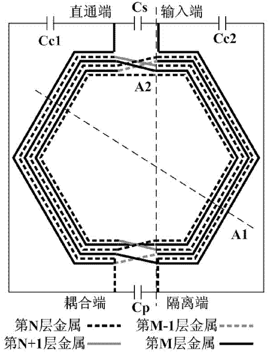
[0033] The integrated directional coupler based on the printed circuit board (PCB) of this embodiment is such as Figure 3 to Figure 5 shown, where image 3 is the top view of the directional coupler layout, Figure 4 for image 3 Sectional view of middle section A1, Figure 5 for image 3 Sectional view of middle section A2.

[0034] Such as image 3 As shown, the directional coupler includes two layers of mutually coupled coils, that is, the first coil (indicated by a solid line) and the second coil (indicated by a dotted line), both of which are hexagonal in shape and are concentric multi-turn structures. The outermost circle (or the innermost circle) leads out the two ends of the coil. The two ends of the first coil are respectively used as the input end and the through end, and the two ends of the second coil are respectively use...


PUM


Abstract

The invention provides a PCB (printed circuit board)-based integrated directional coupler which comprises a first coil, a second coil, two adjustable capacitors and two crossover capacitors. The first coil is formed by winding an Mth layer of metal, and intersection portions are connected by an (M-1)th layer of metal. The second coil is coupled with the first coil, and is formed by winding an Nth layer of metal, and the intersection portions are connected by an (N-1)th layer of metal. N and M are positive integers, wherein N is larger than or equal to 1 and M is larger than or equal to N+2. One of the two adjustable capacitors is connected with an input end and a shoot-through end, and the other one of the two adjustable capacitors is connected with a coupling end and an isolation end. One of the two crossover capacitors is connected with the shoot-through end and the coupling end, and the other one of the two crossover capacitors is connected with the input end and the isolation end. The integrated directional coupler can be integrated on a PCB, and is characterized by small area, low input loss, good coupling degree, sound isolation degree and strong tuning performance.

Description

technical field [0001] The invention belongs to the technical field of radio frequency integrated circuits and relates to a directional coupler, in particular to an integrated directional coupler based on a printed circuit board (PCB). Background technique [0002] Directional Coupler (Directional Coupler) is a widely used radio frequency device, which can be used for signal isolation, signal separation, etc., so that the radio frequency receiver and transmitter can work in the same frequency band at the same time. The principle of directional coupler applied to transceiver system is as follows: figure 1 As shown, "Input" (Input) is connected to the transmitter output (TX), "Direct" (Direct) is connected to the antenna (Antenna), "Coupled" (Coupled) is connected to the receiver input (RX), "Isolation Terminal" (Isolated) is connected to the matching resistor (Res). Among them, the loss between the input end and the through end is "Insertion Loss", the loss between the inpu...

Claims


Application Information

Patent Timeline
Patent Type & Authority Applications(China)
IPC IPC(8): H01P5/18
Inventor 叶乐苗微沈灵廖怀林黄如
Owner PEKING UNIV
Why Eureka
Try Eureka