Supercharge Your Innovation With Domain-Expert AI Agents!

Enhanced flue gas damper mixing device

A mixing device and flue gas technology, which is applied in exhaust gas devices, gas and gas/steam mixing, mixers, etc., can solve problems such as expensive and increased system costs

Active Publication Date: 2013-11-06
GENERAL ELECTRIC TECH GMBH
View PDF3 Cites 1 Cited by
  • Summary
  • Abstract
  • Description
  • Claims
  • Application Information

AI Technical Summary

Problems solved by technology

"Hot spots" require high temperature metals, which are typically more expensive than standard metals
Longer transition sections increase system cost

Method used


Image

  • Enhanced flue gas damper mixing device
  • Enhanced flue gas damper mixing device
  • Enhanced flue gas damper mixing device

Examples


Embodiment Construction

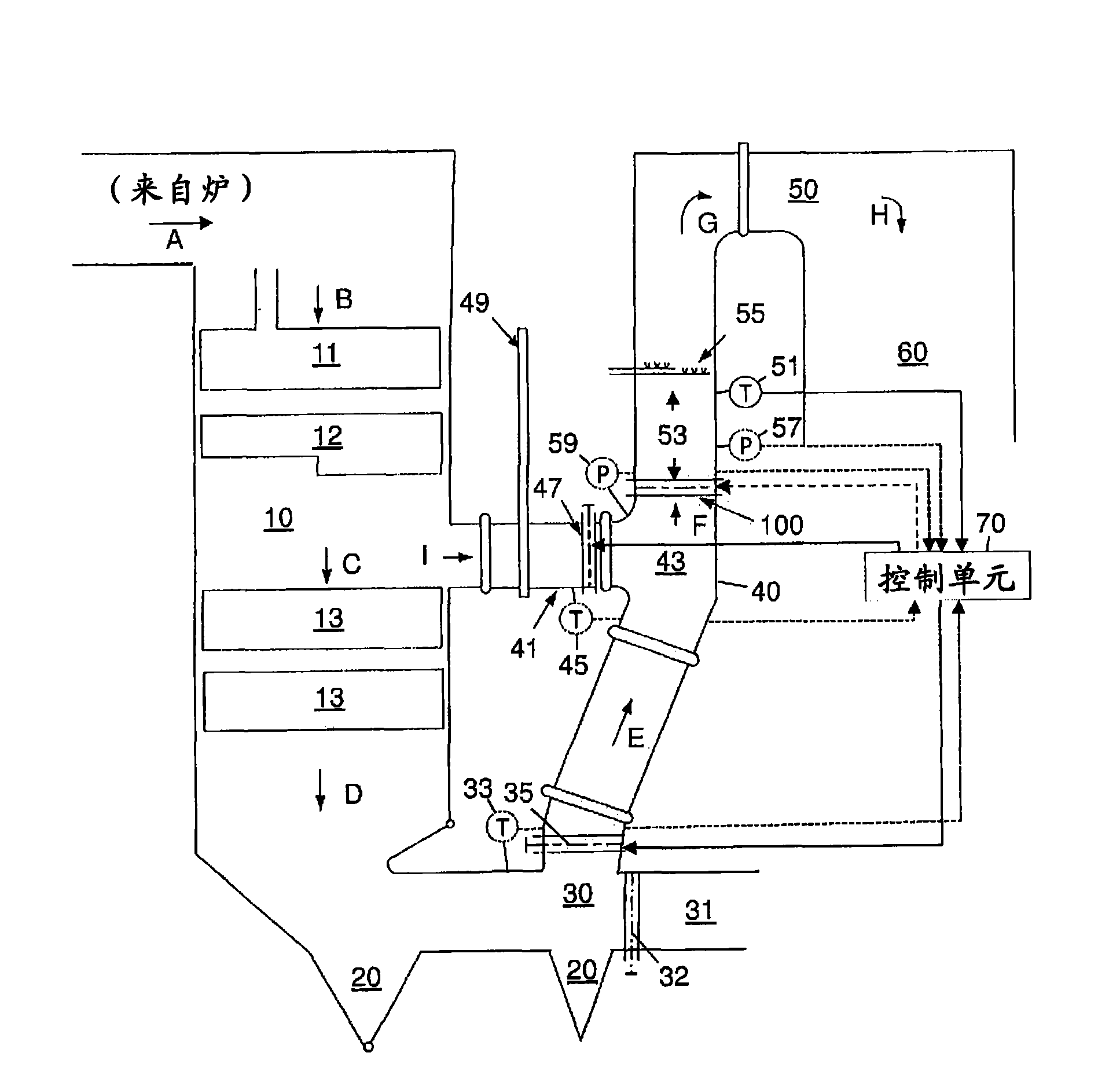
[0031] When the boiler is operating near full capacity, there is little or no gas flow through the bypass, there is effectively only a single gas flow and no mixing is required. As the boiler load decreases, an increasing amount of flue gas must bypass the economizer to maintain the correct flue gas temperature, thereby creating two distinct gas streams. Gas mixing is only required when there are at least two gas streams to be mixed. Prior art designs do not differentiate between different boiler loads and are not adjustable. They therefore have non-adjustable mixers that create a pressure drop at all boiler loads, where the highest pressure drop is created at the highest boiler load where no mixing is required.

[0032] The present invention provides minimal pressure drop when there is effectively only a single gas stream flowing. It is also adjustable to optimize mixing and minimize back pressure across the entire operating range of the steam generator.

[0033] It employ...


PUM


Abstract

A gas mixing device has a plurality of interleaved rows of adjustable louvers. When at least two flowing gas streams are received that are desired to be mixed, the louvers of each row directs the gas streams in a direction different from that of the adjacent rows, mixing the gas streams. When effectively only a single flowing gas stream is received, the louvers are positioned vertically thereby reducing the pressure drop across the gas mixing device.

Description

technical field [0001] The present disclosure discloses an apparatus for efficiently mixing two flowing combustion gas streams and reducing gas back pressure under varying furnace loads. Background technique [0002] Gases of different temperatures are often mixed in many applications, such as in boilers or steam generators. For example, when a boiler's furnace is operating at full load, all the hot flue gas passes through the economizer. The economizer recovers heat from the flue gas to preheat the feed water that is circulated back to the boiler. The resulting exiting flue gas is cooler due to heat transfer. Therefore, heat is recovered into the boiler, thereby increasing boiler efficiency. [0003] However, when the furnace / boiler is operating at low load, if all the flue gas passes through the economizer, the temperature of the flue gas can drop below the critical temperature required for certain chemical processes, such as selecting from Catalytic removal of NO, NO ...

Claims


Application Information

Patent Timeline
Patent Type & Authority Applications(China)
IPC IPC(8): B01F3/02B01F5/00F23J15/00B01F23/10
CPCF22B37/40Y10T137/87652F22B35/001B01D53/00F23J13/00F23J15/00F23J15/02
Inventor M·B·科亨T·D·赫勒威尔
Owner GENERAL ELECTRIC TECH GMBH
Features
  • R&D
  • Intellectual Property
  • Life Sciences
  • Materials
  • Tech Scout
  • Unparalleled Data Quality
  • Higher Quality Content
  • 60% Fewer Hallucinations
Learn More