
Oil supply control lubrication system for gearbox

A lubrication system and oil supply control technology, applied in the direction of gear lubrication/cooling, etc., can solve the problems of hydraulic transmission box structure size increase, large external size, oil and gas leakage, etc., to avoid oil leakage and pollution of hydraulic oil, Effects of reduced external dimensions and reduced power loss

Active Publication Date: 2015-11-18
CRRC DALIAN INST CO LTD
View PDF6 Cites 2 Cited by
  • Summary
  • Abstract
  • Description
  • Claims
  • Application Information

AI Technical Summary

Problems solved by technology

[0007] 1) The oil supply pump and inert pump in the hydraulic transmission box absorb oil directly from the oil pool of the box body, and the power loss is relatively large
[0008] 2) The transmission power in the hydraulic transmission box is the hydraulic oil, so the demand for the flow of the hydraulic oil is very large. In order to meet the large flow, the oil supply pump is a centrifugal vane pump, and the inertia pump and control pump are external gear pumps. , its external dimensions are very large, which increases the structural size of the hydraulic transmission box
[0009] 3) The main control valve in the hydraulic transmission box is controlled by compressed air. Since the operating cylinder is located inside the box, it is easy to leak, and the compressed air enters the inside of the box, resulting in an excessive internal and external pressure difference, which easily causes oil and gas to leak from the box. At the same time, the moisture in the compressed air will also pollute the hydraulic oil in the tank

Method used


Image

  • Oil supply control lubrication system for gearbox

Examples


Embodiment Construction

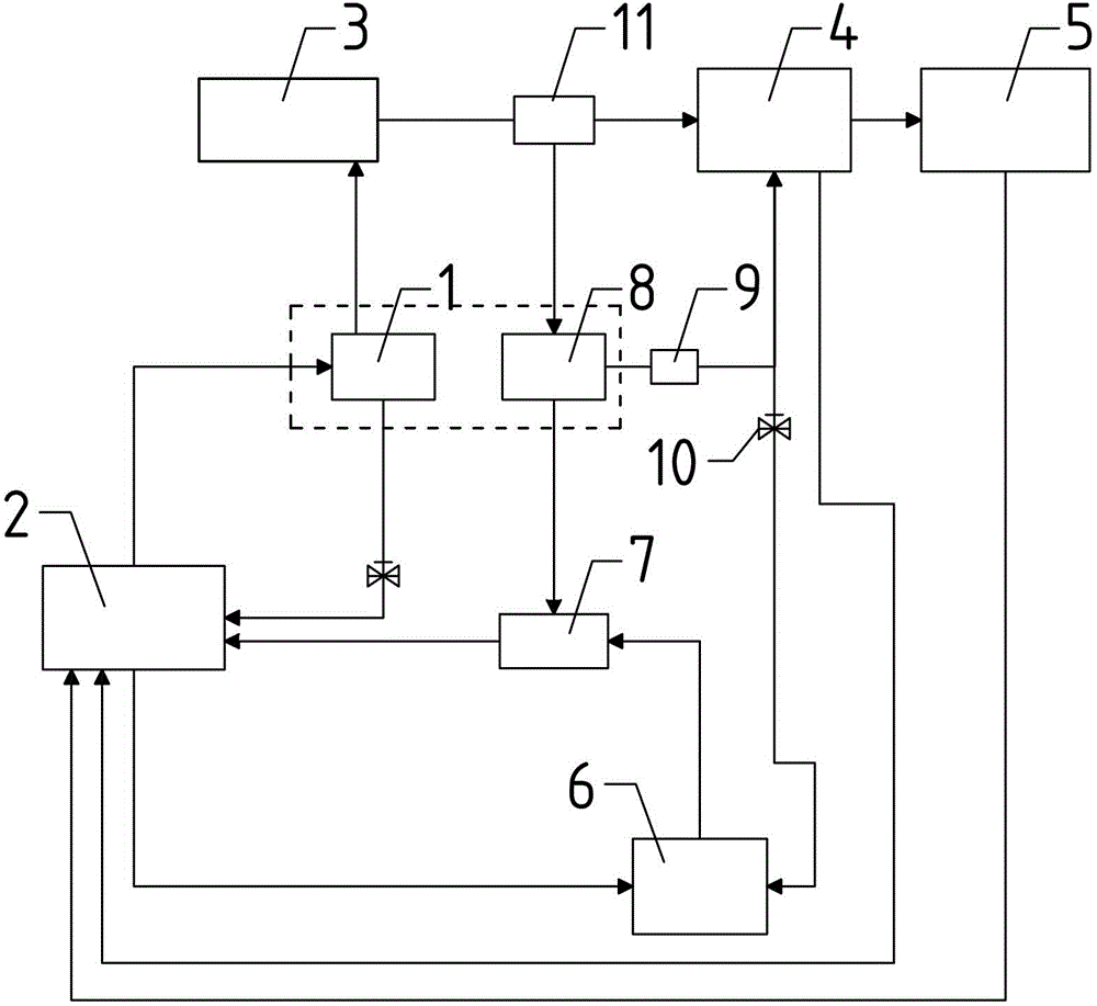
[0021] Such as figure 1 The oil supply control lubrication system for the transmission box shown includes: oil supply pump 1, oil tank 2, heat dissipation system 3, main control valve 4, hydraulic component 5, inert pump 6 and lubrication system 7, and also includes: control pump 8;

[0022] The oil supply pump 1 draws hydraulic oil from the oil tank 2 and sends it to the heat dissipation system 3 through a pipeline, and the oil returned to the mailbox by the oil supply pump 1 communicates with the mailbox 2 through a pipeline with a one-way valve;

[0023] The heat dissipation system 3 passes the filter 11 through the pipeline to transport the cooling hydraulic oil back to the transmission box and then enters different oil paths. One is directly into the hydraulic element 5 to participate in the transmission of power, and the other is to connect to the oil supply pipeline of the control pump 8. Furthermore, it is ensured that the incoming oil of the control pump 8 is pressure oil,...


PUM


Abstract

The invention discloses an oil supply control lubrication system for a transmission case. An oil supply pump feeds hydraulic oil in an oil tank into a heat radiation system to perform cooling, cooled hydraulic oil returns to the transmission case and then flows into different oil ways, one oil way is that the cooled hydraulic oil directly flows into a hydraulic element to participate in power transmitting, and the other oil way is that the oil is supplied for a control pump. The hydraulic oil pumped by the control pump is subjected to refined filtration and divided into two ways, one way is that the hydraulic oil serving as control oil is provided for a main control valve, and the other way is that the hydraulic oil flows into the lubrication system. Oil for an inert pump is supplied through two oil ways, one oil way is that the oil is sucked from the oil tank, and the other oil way is that the oil of an outlet of the control pump flows into an inlet of the inert pump through a one-way valve and then directly enters the lubrication system through the inert pump. By adopting the technical scheme and a reasonable allocation scheme, the problems including pump power loss and oil-gas leakage from a tank body in the prior art are solved.

Description

Technical field [0001] The invention relates to a mechanical lubrication system, in particular to an oil supply control lubrication system for a transmission box. Background technique [0002] The existing oil supply control lubrication system for the hydraulic transmission box mainly provides working oil for transmitting power and lubricating and cooling gears and bearings for the transmission box; in addition, the heat converted into the power loss during the operation of the transmission box is taken away to ensure the transmission The temperature of the working oil does not exceed the specified range; at the same time, the gas path is used to control the gear shifting, reversing, and controlling the operation of the locomotive. [0003] Common solutions are: [0004] After the hydraulic oil in the hydraulic transmission box enters the heat exchange system for cooling by the oil supply pump, it reaches the main control valve, and the main control valve acts to control the hydraul...

Claims


Application Information

Patent Timeline
Patent Type & Authority Patents(China)
IPC IPC(8): F16H57/04
Inventor 张英爽庞洁王贺鹏
Owner CRRC DALIAN INST CO LTD
Learn More