Milling cutter for hard machining

A milling process and milling cutter technology, applied in the field of milling cutters, can solve problems such as tool failure, high cutting edge, and uncertainty

Inactive Publication Date: 2013-11-06
CERAMTEC
View PDF5 Cites 4 Cited by
  • Summary
  • Abstract
  • Description
  • Claims
  • Application Information

AI Technical Summary

Problems solved by technology

Deformation and jamming processes are severe and can lead to high, undefined loads of the cutting edge on the cutting edge part
These loads can lead to uncontrolled tool failure mainly when milling harder materials through hard cutting materials such as cBN and PcBN

Method used


Image

  • Milling cutter for hard machining
  • Milling cutter for hard machining
  • Milling cutter for hard machining

Examples


Embodiment Construction

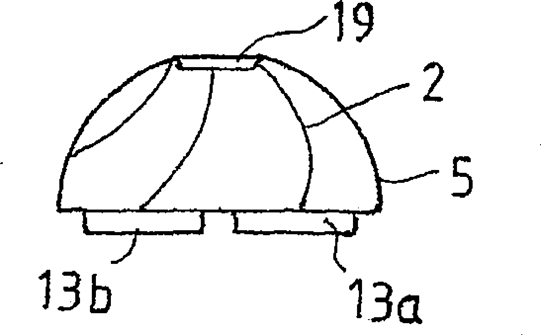
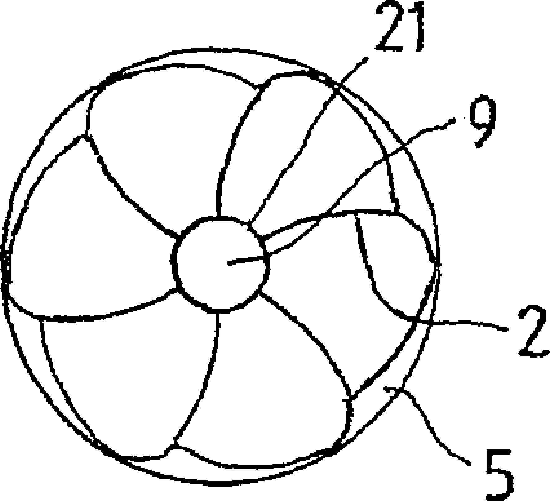
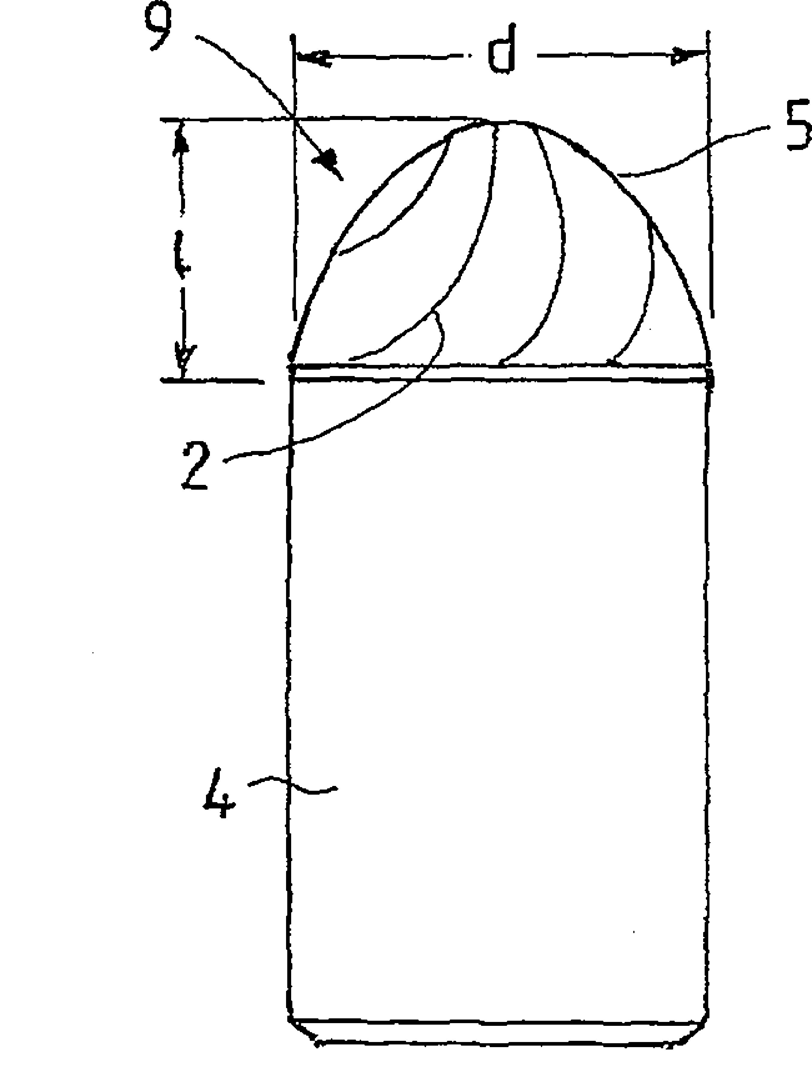
[0033] FIG. 1 shows a longitudinal section of a milling cutter 1 made of a base body 4 and a hemispherical cutting edge part 5 welded to the base body 4 on which the cutting edge 2 is arranged. The milling cutter 1 is mounted for use on a milling machine (not shown). Milling cutter has length l gesamt and diameter d gesamt . The base body 4 and the cutting edge part 5 are formed cylindrically. Base body 4 is made of hard metal or of ceramic.

[0034] The cutting edge part 5 is made entirely of polycrystalline cubic boron nitride (PcBN) or polycrystalline diamond (PKD). The cutting edge part 5 has the same diameter d as the base body 4 gesamt . This diameter is 7mm to 40mm. The cutting edge 2 is formed integrally with the cutting edge member 5 . However, the cutting edge 2 can also be welded to the cutting edge part 5 .

[0035] For form-locking fastening of the cutting edge part 5 on the base body 4, on the bottom side of the cutting edge part 5 facing the base body 4...


PUM

PropertyMeasurementUnit
diameteraaaaaaaaaa

Abstract

The invention relates to a milling tool (1) having a length Itotal and diameter dtotal and having blades (2) for the milling of mostly metal workpieces. In order to prevent an uncontrolled failure of the milling tool, it is proposed that the blades (2) are partially or entirely made of polycrystalline cubic boron nitride (PcBN) or polycrystalline diamond (PCD) and the diameter dtotal of the milling tool lies between 7 mm and 40 mm.

Description

technical field [0001] The invention relates to a milling cutter having a length l gesamt and diameter d gesamt , and has a cutting edge for milling most metal workpieces. Background technique [0002] These milling cutters are used for machining spherical raceways in the bearing industry, transmission and drive technology, mold making and general machine construction. [0003] Spherical raceways are generally produced by milling in the soft state, heat treatment and milling in the hard state. During milling, the cutting speed at the center of the spherical raceway or at the axis of rotation of the cutting edge part or milling cutter is zero, ie vc=0m / min. So-called ball nose cutters are used. [0004] Cutting properties are indeterminate at this location. The deformation and clogging processes are severe and can lead to high and undefined loads of the cutting edge on the cutting edge part. These loads can lead to uncontrolled tool failure, mainly when milling harder m...

Claims


Application Information

Patent Timeline
Patent Type & Authority Applications(China)
IPC IPC(8): B23C5/10
CPCB23C2210/207B23C2210/03B23C5/1009B23C2226/125B23C2210/209B23C5/1081B23C2210/203B23C2210/205B23C2240/08B23C2240/32B23C2226/315B23C2210/02B23C2210/208Y10T407/1904Y10T407/1946Y10T407/1906
Inventor R.本阿莫尔
Owner CERAMTEC
Why Eureka
Try Eureka