High temperature dust collector

A vacuum cleaner and high temperature technology, which is applied in the field of glass production equipment, can solve problems such as easy to cause dust, high flue temperature, and back-end equipment operation failure, and achieve the effect of ensuring non-stick and wide application range

Inactive Publication Date: 2013-11-13
HUAERRUN GLASS IND
View PDF3 Cites 2 Cited by
  • Summary
  • Abstract
  • Description
  • Claims
  • Application Information

AI Technical Summary

Problems solved by technology

[0002] The existing glass furnace and its flue have high temperature and a large amount of dust accumulation. The traditional cleaning method is to manually clean the flue opening with a long-handled tool after cooling down. The working environment is poor, and the labor intensity of the workers is high. Due to the negative pressure in the flue, it is easy to cause dust during the cleaning process, and part of the ash enters the back-end part with the flue, which is likely to cause the operation failure of the back-end equipment, thereby affecting production
[0003] Due to the limitation of the material of the filter bag, the traditional high-temperature vacuum cleaner usually controls the working temperature within 500°C, and can withstand a high temperature of 1000°C at the moment, but cannot work at a high temperature above 500°C for a long time.
In the glass kiln using solid fuel and the flue of a power plant, the temperature of the air sucked by the high-temperature vacuum cleaner is 600-1000°C, so the existing high-temperature vacuum cleaner is difficult to apply
In addition, due to the limitation of its own structure, the existing high-temperature vacuum cleaner has a small dust collection capacity and cannot meet the requirements of use.
[0004] In addition, the filter bags in traditional high-temperature vacuum cleaners are usually made of ordinary materials. Due to the low temperature resistance of the filter bags during work, the filter bags are often damaged and cannot work normally. This not only increases maintenance costs, but also increases the work of maintenance workers. quantity

Method used


Image

  • High temperature dust collector

Examples


Embodiment 1

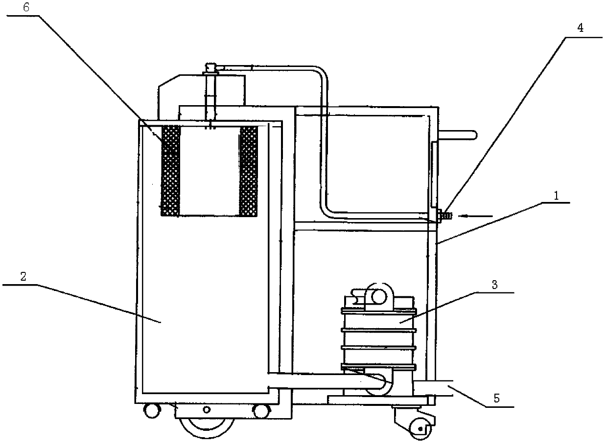
[0015] Hot vacuum cleaners, see figure 1 , including the body (1) and the air chamber (2), the fan (3), the air inlet pipe (4), the air outlet pipe (5), and the metal filter screen (6) arranged in the body (1), the air inlet pipe ( 4), the air chamber (2) is connected with the fan (3) and the air outlet pipe (5) in sequence, and the metal filter (6) is arranged between the air inlet pipe (4) and the air inlet of the air chamber (2).

[0016] The metal filter screen (6) is a 304 stainless steel metal filter screen with a gap of 400 meshes. It has been proved by long-term use that it can continuously withstand high temperatures of 800°C without deformation.

Embodiment 2

[0018] The high-temperature vacuum cleaner is basically the same as in Example 1, except that the metal filter (6) is a 316 stainless steel metal filter with a gap of 200 meshes. It has been proved by long-term use that it can continuously withstand high temperatures of 1000°C without out of shape.

Embodiment 3

[0020] The high-temperature vacuum cleaner is basically the same as that in Embodiment 1, except that the metal filter screen (6) is a high-temperature-resistant metal alloy filter screen with a gap of 200 meshes.


PUM

PropertyMeasurementUnit
sizeaaaaaaaaaa

Abstract

The invention provided with a high temperature dust collector. The high temperature dust collector comprises a body (1) and an air chamber (2) arranged in the body (1), a fan (3), an air inlet pipe (4), an air outlet pipe (5) and a metal screen (6), wherein the air inlet pipe (4), the air chamber (2), the fan (3) and the air outlet pipe (5) are successively connected, and the metal screen (6) is arranged between the air inlet pipe (4) and an air inlet of the air chamber (2). The high temperature dust collector provided by the invention has the characteristics that a filter bag which is made of a metal material is adopted to replace the traditional filter bag, the high temperature dust collector is high temperature resistance and is easy to clean, and the application range is wide.

Description

technical field [0001] The invention belongs to the field of glass production equipment, in particular to a high-temperature vacuum cleaner. Background technique [0002] The existing glass furnace and its flue have high temperature and a large amount of dust accumulation. The traditional cleaning method is to manually clean the flue opening with a long-handled tool after cooling down. The working environment is poor, and the labor intensity of the workers is high. Due to the negative pressure in the flue, it is easy to cause dust during the cleaning process, and part of the ash enters the back-end part with the flue, which is likely to cause the back-end equipment to malfunction, thereby affecting production. [0003] Due to the limitation of the material of the filter bag, the traditional high-temperature vacuum cleaner usually controls the working temperature within 500°C, and can withstand a high temperature of up to 1000°C in an instant, but cannot work at a high temper...

Claims


Application Information

Patent Timeline
Patent Type & Authority Applications(China)
IPC IPC(8): C03B5/16
Inventor 戴子剑张奎
Owner HUAERRUN GLASS IND
Why Eureka
Try Eureka