Scroll fluid machine
A fluid machinery and scroll technology, used in rotary piston machinery, mechanical equipment, liquid fuel engines, etc., can solve problems such as inability to use and deterioration of blade end seal wear, and achieve the effect of inhibiting wear and avoiding pressing.
- Summary
- Abstract
- Description
- Claims
- Application Information
AI Technical Summary
Problems solved by technology
Method used
Image
Examples
Embodiment approach 1
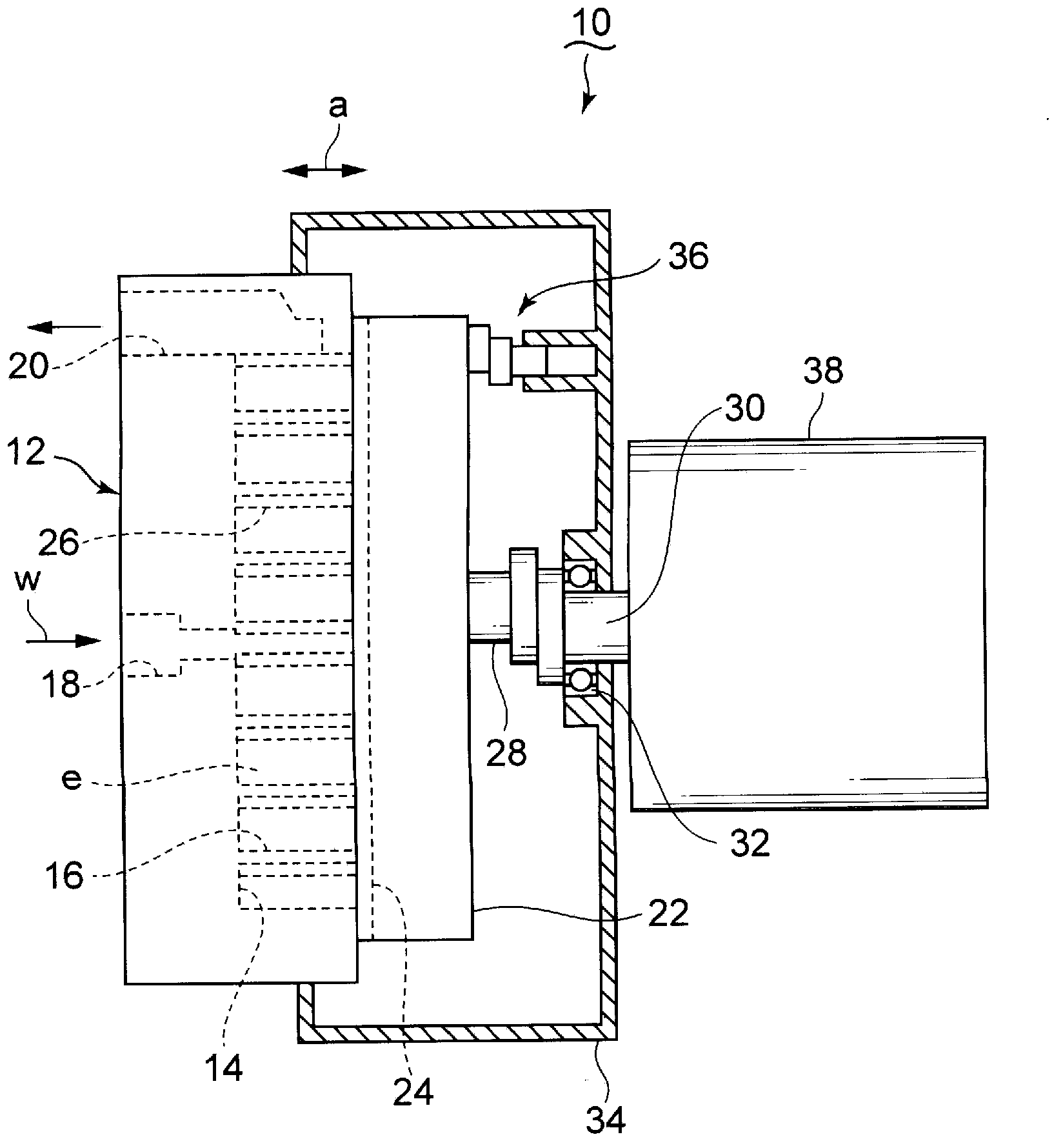
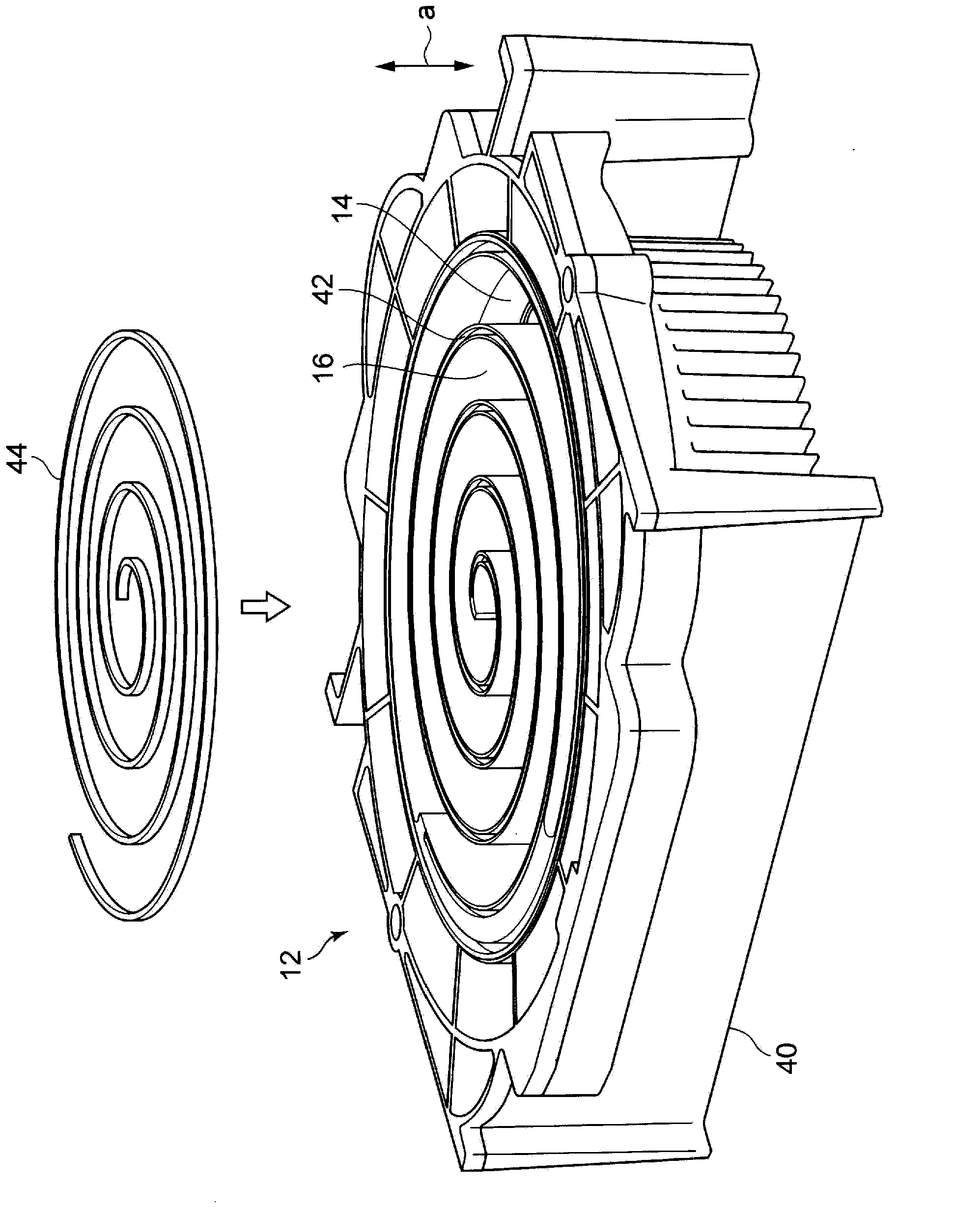
[0044] based on Figure 1 ~ Figure 3 A first embodiment in which the present invention is applied to a scroll expander will be described. exist figure 1 In the scroll expander 10, a fixed scroll body 12 and an orbiting scroll body 22 are disposed opposite to each other. The fixed scroll 12 includes an end plate 14 and a spiral wrap 16 erected from the end plate 14 in the axial direction a of the scroll expander 10 . The orbiting scroll 22 includes an end plate 24 and a spiral wrap 26 erected from the end plate 24 in the axial direction a. The coiled plate 16 and the coiled plate 26 are in linear contact, and a plurality of expansion chambers e are formed by the end plates 14 , 24 and the coiled plates 16 , 26 . A plurality of expansion chambers e are formed on both sides of the coiled plates 16, 26 toward the outer peripheral side.
[0045] The center shaft 28 of the orbiting scroll 22 is attached at a position eccentric to the crankshaft 30 , and performs orbital motion ...
Embodiment approach 2
[0056] Next, use Figure 4 Next, the second embodiment of the device of the present invention will be described. In the present embodiment, a space with a square cross section is provided between the bottom surface 44d of the tip seal 44 and the groove inner bottom surface 16d of the wrap 16, and the space is filled with a square cross section made of rubber, an elastic body, or the like. Elastic member 48 . The rest of the structure is the same as that of the above-mentioned first embodiment.
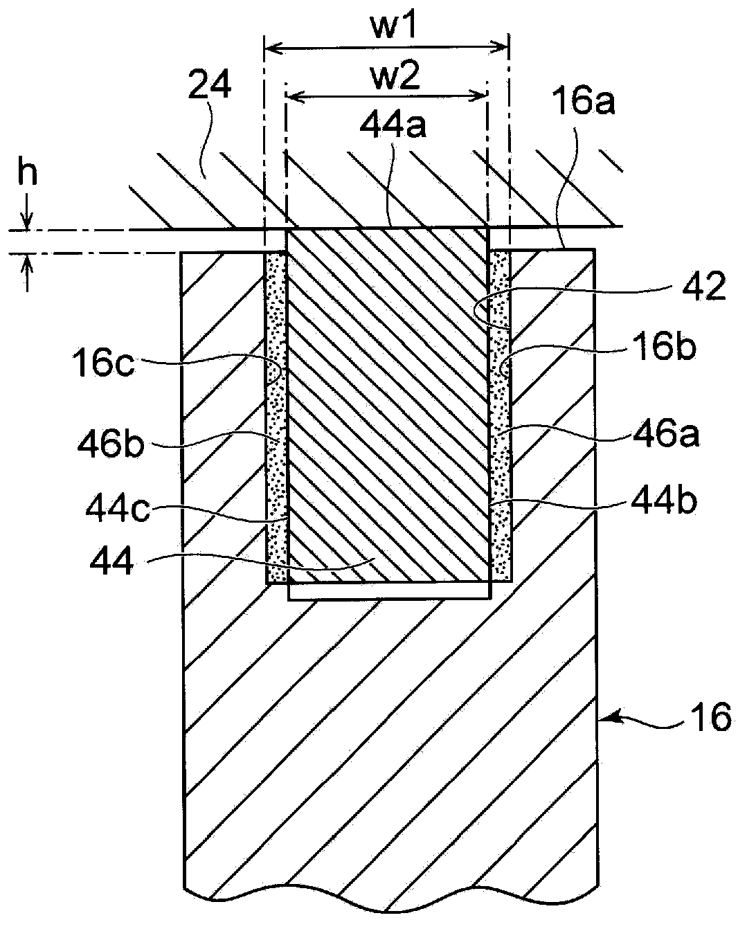
[0057] In this embodiment, the upper surface 44a of the tip seal 44 is pressed against the end plate 24 by the pressing force of the elastic member 48 before the swelling members 46a, 46b are swelled by liquefaction of the working medium or the like. The axial position of the tip seal 44 is fixed by the swelling members 46a, 46b after the swelling members 46a, 46b are swelled by liquefaction of the working medium or the like.
[0058] Therefore, before the swelling members 46a, 46b ...
Embodiment approach 3
[0060] Next, use Figure 5 The third embodiment of the device of the present invention will now be described. In this embodiment, instead of the swelling members 46a and 46b of the first embodiment, a groove 52 having a quadrangular cross-section is carved on the right side surface 50b of the tip seal 50 . A rod-shaped swelling element 54 with a circular cross section is inserted into the groove 52 . The swelling member 54 is arranged in a spiral shape in the entire longitudinal range of the coiled plate 16 . In this structure, the swelling member 54 is interposed between the side surface 52a of the groove 52 and the right side surface 16b in the groove of the roll plate 16 opposite to the same side surface 52a. The swelling member 54 is made of styrene-butadiene rubber or butyl rubber, and the above-mentioned rubber has the property of swelling by absorbing the condensate of the working medium w and the condensed water of the water vapor contained in the working medium. Ot...
PUM
 Abstract
Description
Claims
Application Information
 - R&D
- Intellectual Property
- Life Sciences
- Materials
- Tech Scout
- Unparalleled Data Quality
- Higher Quality Content
- 60% Fewer Hallucinations
Browse by: Latest US Patents, China's latest patents, Technical Efficacy Thesaurus, Application Domain, Technology Topic, Popular Technical Reports.
© 2025 PatSnap. All rights reserved.Legal|Privacy policy|Modern Slavery Act Transparency Statement|Sitemap|About US| Contact US: help@patsnap.com


