MT (magnetotelluric) denoising device and method

A magnetotelluric and electromagnetic technology, applied in the field of electrical prospecting, can solve problems such as no method to rely on, high human factors, etc., and achieve the effect of improving credibility

Active Publication Date: 2013-11-13
乌兰察布工业技术研究院有限公司
View PDF5 Cites 18 Cited by
  • Summary
  • Abstract
  • Description
  • Claims
  • Application Information

AI Technical Summary

Problems solved by technology

However, the above is not completely effective, and sometimes suppresses some useful signals while suppressing interference noise
Therefore, artificial denoising is still an indispensable mea

Method used


Image

  • MT (magnetotelluric) denoising device and method
  • MT (magnetotelluric) denoising device and method
  • MT (magnetotelluric) denoising device and method

Examples


Embodiment 1

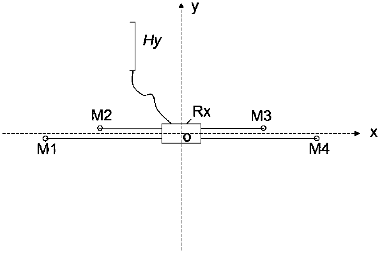
[0051] Such as figure 1 As shown, Embodiment 1 provides a magnetotelluric denoising measurement device, which is a magnetotelluric denoising measurement device based on scalar measurement mode, arranged in the xy coordinate system established with the measurement point as the center point, and can be applied to Natural source magnetotelluric denoising survey or controlled source magnetotelluric denoising survey. Its structure includes:

[0052] An electromagnetic receiver Rx placed on the ground is used to read magnetic field amplitude data and electric field amplitude data;

[0053] A magnetic induction sensor Hy placed on the ground along the direction of the parallel y-coordinate axis, which is connected with the electromagnetic receiver Rx through a cable for measuring magnetic field amplitude data;

[0054] A group of non-polarized electrode groups M1, M2, M3, and M4 are placed symmetrically on the ground along the x-axis with the origin of the coordinate system as the ...

Embodiment 2

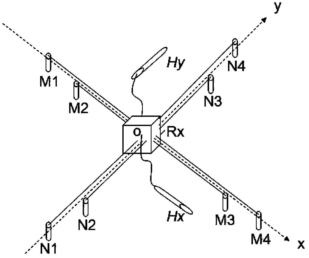
[0063] Such as image 3 As shown, Embodiment 2 provides a magnetotelluric denoising measurement device in vector measurement mode, which is also arranged in the xy coordinate system established with the measurement point as the center point, and can be applied to natural source magnetotelluric denoising measurements or can be Controlled source magnetotelluric denoising measurements. The device in Embodiment 2 is constructed based on the magnetotelluric denoising measurement device used in the scalar measurement mode in Embodiment 1. It only needs to add a set of measurement devices in the scalar measurement mode, and make it rotate 90° with the measurement center o as the axis Spend. The specific structure is:

[0064] An electromagnetic receiver Rx placed on the ground is used to read magnetic field amplitude data and electric field amplitude data;

[0065] A pair of magnetic induction sensors Hx and Hy placed parallel to the ground along the horizontal x and y coordinate ...


PUM


Abstract

The invention relates to an MT denoising device which comprises an electromagnetic receiver, a magnetic induction sensor and a non-polarizable electrode group, wherein the electromagnetic receiver is placed on the ground; the magnetic induction sensor is placed on the ground in a direction parallel to an x axis or a y axis and connected with the electromagnetic receiver through a cable; the non-polarizable electrode group takes a coordinate system origin as a central point, is placed symmetrically along the y axis or the x axis and grounded, and comprises a first long pole pitch electric dipole and a first short pole pitch electric dipole; the first long pole pitch electric dipole is used for measuring amplitude data of a long pole pitch electric field, and the first short pole pitch electric dipole is used for measuring amplitude data of a short pole pitch electric field; and all non-polarizable electrodes are connected with the electromagnetic receiver through wires. The device is used for calculating the correlation coefficient and the standard deviation between the amplitude data of the long pole pitch electric field and the short pole pitch electric field, when the correlation coefficient is smaller than a set correlation threshold, electric field amplitude data with largest standard deviation are removed, the correlation coefficient is calculated repeatedly until the correlation coefficient is larger than or equal to the set correlation threshold, and near field interference data are effectively removed.

Description

technical field [0001] The invention relates to the field of electrical prospecting, in particular to a magnetotelluric denoising device and a magnetotelluric denoising method which use a data correlation analysis method to judge the nature of a field source and remove interference noise. Background technique [0002] As an important exploration geophysical method, the magnetotelluric method has a wide range of applications and many branches. Since the first proposal, the audio frequency magnetotelluric method (AMT) was proposed in the 1960s. In 1971, Professor D.W.Strangbway of the University of Toronto in Canada and his graduate student Myron Goldstein proposed the Controlled Source Audio Magnetotelluric Method (CSAMT). These methods (MT, AMT, CSAMT) all determine the resistivity value of the subsurface by observing the electric and magnetic field signals of natural plane electromagnetic waves caused by far-field sources. Among them, the geoelectric field observation res...

Claims


Application Information

Patent Timeline
IPC IPC(8): G01V3/08G01V3/38
Inventor 于昌明邢宝山
Owner 乌兰察布工业技术研究院有限公司
Why Eureka
Try Eureka