3D (Three Dimensional) display equipment and method based on electric-induced refractive index conversion

A display device and display method technology, applied in optics, instruments, nonlinear optics, etc., can solve the problems of high production cost, complex structure, and high cost, and achieve the effect of low cost, small volume, and simple structure

Inactive Publication Date: 2013-11-13
QIANHAI EIDAOLON TECH SHENZHEN CO LTD
View PDF4 Cites 5 Cited by
  • Summary
  • Abstract
  • Description
  • Claims
  • Application Information

AI Technical Summary

Problems solved by technology

[0012] Holographic 3D technology and volumetric 3D display technology Compared with Barrier, Lenticular Lens technology, and Directional Backlight 3D display technology, each pixel or the image of each pixel is not on the same plane In addition, it has a real depth of field, so when watching 3D images, users will not have side effects such as dizziness, headache, and eye fatigue, and the resolution and brightness of the screen will not be reduced, and there is not much restriction on the vision and angle of viewing 3D images , but because the structure of the stereoscopic three-dimensional display device is much more complicated than that of the ordinary 2D display device, and due to the structural factors, the volume is larger, the cost is higher, and it is not compatible with the existing LCD panel, so the development more expensive to produce

Method used


Image

  • 3D (Three Dimensional) display equipment and method based on electric-induced refractive index conversion
  • 3D (Three Dimensional) display equipment and method based on electric-induced refractive index conversion
  • 3D (Three Dimensional) display equipment and method based on electric-induced refractive index conversion

Examples


Embodiment 1

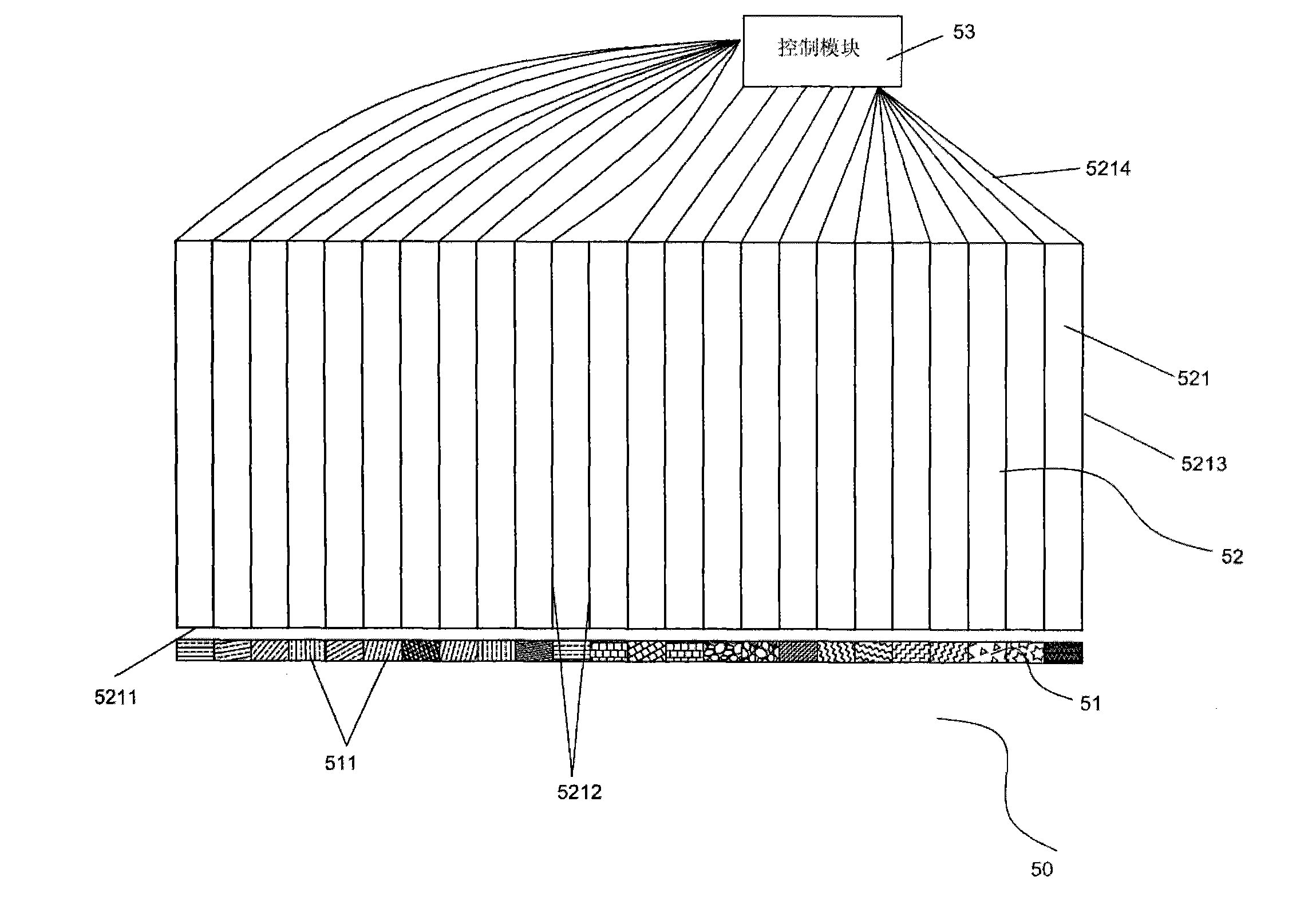
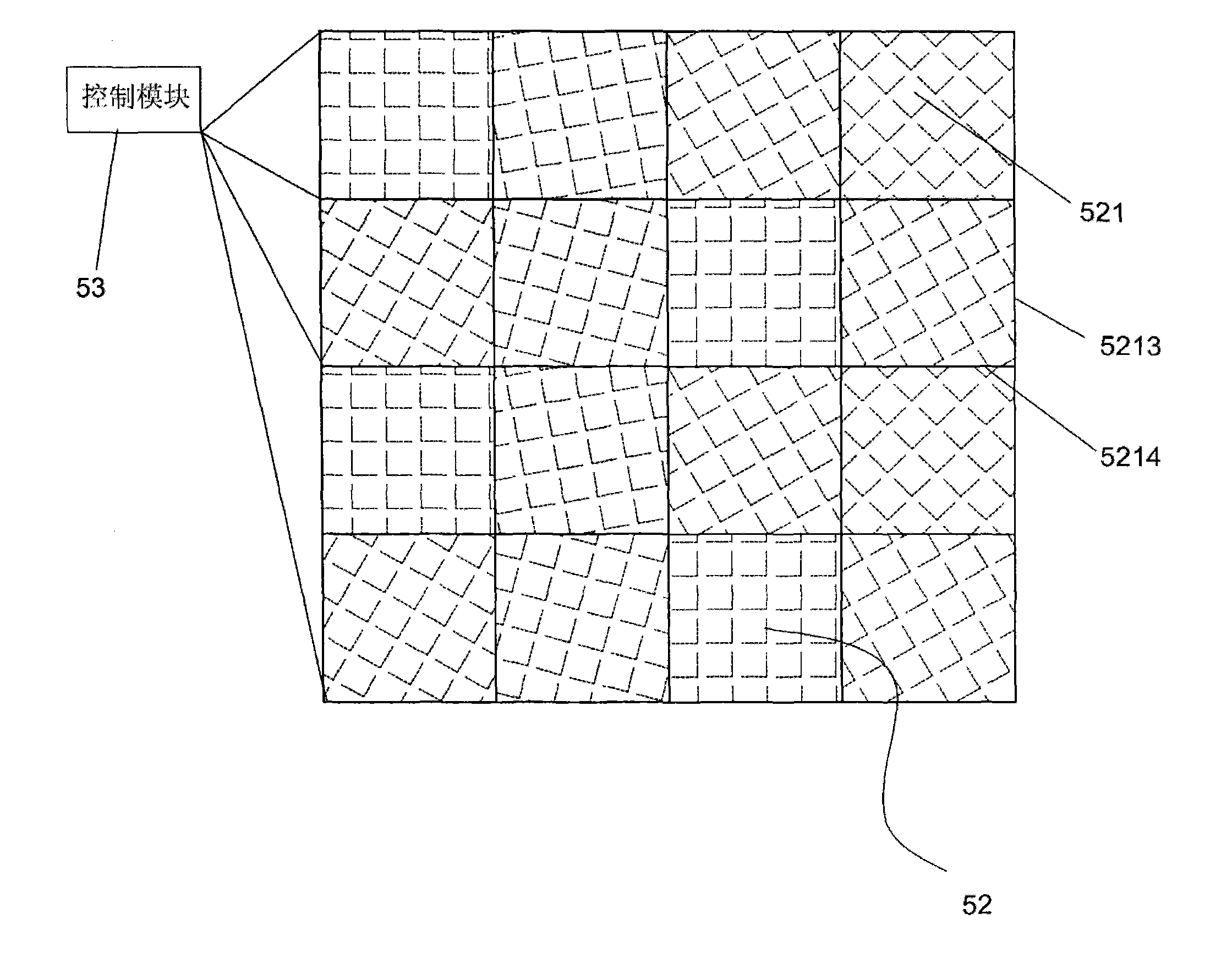
[0047] Such as Figure 2-4 As shown, the present embodiment provides a kind of 3D display device 50 based on electro-induced refractive index change, and the device 50 includes a two-dimensional liquid crystal panel display 51, and one is arranged on the front end of the display screen 51 (that is, the display screen 51 displays The front of the surface) is a plate-shaped transparent electro-optic crystal array 52. ​​The electro-optic crystal array 52 is composed of a plurality of electro-optic crystals 521 of the same shape and size. The shape of each electro-optic crystal 521 is a rectangular parallelepiped column, and the columnar The bottom surface is square, and the bottom surface 5211 of the columnar body is opposite to the display screen 51. The liquid crystal panel display screen 51 includes a plurality of square pixel points 511 of the same size, and the ground 5211 of the columnar body is the same size as the pixel point 511. Opposite to each pixel point 511, two pla...


PUM


Abstract

The invention provides 3D (Three Dimensional) display equipment based on electric-induced refractive index conversion. The equipment comprises a two-dimensional plane display screen and a flat-plate-shaped transparent electro-optical crystal array arranged on the front end of the display screen, wherein the electro-optical crystal array is formed by square-column-shaped electro-optical crystals which are the same as display screen pixel points in quantity; a section of each electro-optical crystal, which is parallel to the display screen, is the same as each display screen pixel point in size; each electro-optical crystal is over against each display screen pixel point; the 3D display equipment further comprises a transparent electrode for applying voltage to each electro-optical crystal and a control module which is electrically connected with the electrode; and the control module is used for controlling the electrode to apply voltage which corresponds to field depth of the pixel points over against the electro-optical crystals to the electro-optical crystals. An image displayed by the 3D display equipment disclosed by the invention can be watched by naked eyes; the resolution ratio and the brightness of a displayed three-dimensional image are not changed; and the displayed three-dimensional image has the real physical field depth.

Description

【Technical field】 [0001] The invention belongs to the technical field of three-dimensional display, and relates to a 3D display device and a display method based on electro-induced refractive index change. 【Background technique】 [0002] 3D, also known as three-dimensional stereo or three-dimensional, 3D imaging technology is different from two-dimensional plane imaging technology, compressing three-dimensional image information into a two-dimensional plane will inevitably distort the image, and it is impossible to prepare each pixel in the reaction image The real space position, the three-dimensional image displayed on the two-dimensional plane is expressed by the light and shade of the color, the size of the object and other information. Judging the distance of each pixel in the two-dimensional plane from the human eye, rather than the real physical depth of field. [0003] The difference between three-dimensional display and two-dimensional display is to use various meth...

Claims


Application Information

Patent Timeline
IPC IPC(8): G02F1/03G02B27/22
CPCG02B27/22G02F1/03G02B27/2221G02B27/2292G02B30/27G02F1/0305G02F1/0327G02F2202/20G02B30/40G02B30/56G02F1/0316G02F1/0322G02F1/134336G02F2201/44
Inventor 冯林
Owner QIANHAI EIDAOLON TECH SHENZHEN CO LTD
Why Eureka
Try Eureka