

Integral reactor passive reactor cavity runner system and application method thereof
A reactor cavity and reactor technology, applied in the direction of reactors, nuclear power generation, reduction of greenhouse gases, etc., can solve the problems of non-integrated reactors, etc., and achieve the effects of improving safety performance, reducing pressure, and maintaining integrity
- Summary
- Abstract
- Description
- Claims
- Application Information
AI Technical Summary
Problems solved by technology
Method used
Image

Examples
Embodiment 1
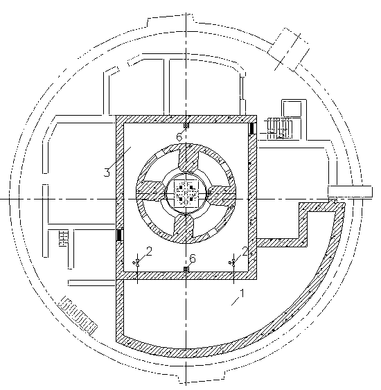
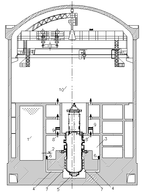
[0027] Such as figure 1 , 2 shown.
[0028] The integrated reactor passive reactor cavity flow channel system includes the reactor cavity 3 and the reactor pit 5, and the annular main shielding wall between the reactor cavity 3 and the reactor pit 5, the reactor pit 5 is located under the main shielding wall, and the reactor The cavity 3 is located above the main shielding wall; the reactor cavity 3 and the reactor pit 5 are connected through the flow channel 4, and the end of the flow channel 4 close to the reactor pit 5 is provided with a windshield 7, and the top of the reactor cavity 3 has a gas release hole 8, Such as figure 2 As shown, the reactor pressure vessel is installed in the annular space of the main shielding wall.
[0029] The traditional reactor has no flow channel 4, and the flow channel of the present invention is connected with the outside or the cooling water source inside the reactor building. When an accident occurs, the cooling water source is quic...
Embodiment 2
[0044] Such as figure 1 , 2 shown.
[0045] The integrated reactor passive reactor chamber flow passage system of the present invention includes an isolation valve 2, an L-shaped flow passage, a circular or square reactor chamber 3, a circular or square reactor pit 5, and a gas release hole 8. Reactor chamber area about 150m 2 , the clearance height is about 6m.
[0046] When a LOCA accident occurs, the reactor cavity is filled with a large amount of steam. After the high-pressure and medium-pressure safety injection to the reactor is completed, the isolation valve 2 is opened, and the water capacity is about 1200m 3 After the built-in refueling water tank 1 injects water into the reactor cavity 3 by gravity, the water flows into the reactor pit 5 through two flow channels 4 with a flow cross section of 400mm×400mm. With the accumulation of injected water, the submerged water level gradually rises, gradually submerging the reactor pit and the reactor cavity, and finally re...
PUM
 Abstract
Description
Claims
Application Information