Tilting runner apparatus for molten iron

A pouring ditch and molten iron technology, applied in lighting and heating equipment, manufacturing converters, furnace components, etc., can solve problems such as the inability to lift the pouring ditch, and achieve the effect of easy position adjustment and unloading

Active Publication Date: 2013-11-13
JFE STEEL CORP
View PDF5 Cites 0 Cited by
  • Summary
  • Abstract
  • Description
  • Claims
  • Application Information

AI Technical Summary

Problems solved by technology

In this case, since the two tapping troughs are arranged at positions facing each other, even if the pouring trough and the trolley are moved to the front of any one of the tapping troughs in the longitudinal direction, the other tapping trough will below, so the pouring ditch cannot be lifted directly to the top

Method used


Image

  • Tilting runner apparatus for molten iron
  • Tilting runner apparatus for molten iron
  • Tilting runner apparatus for molten iron

Examples


Embodiment Construction

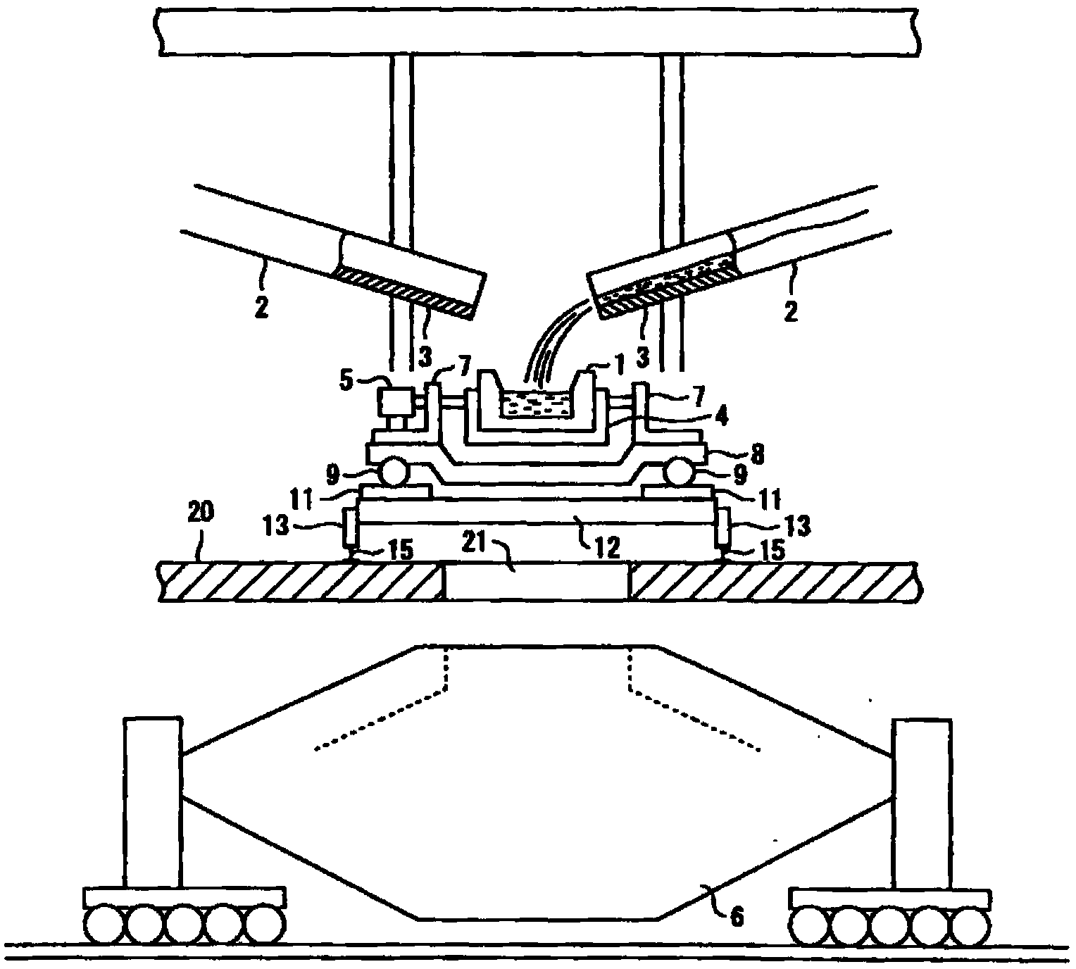
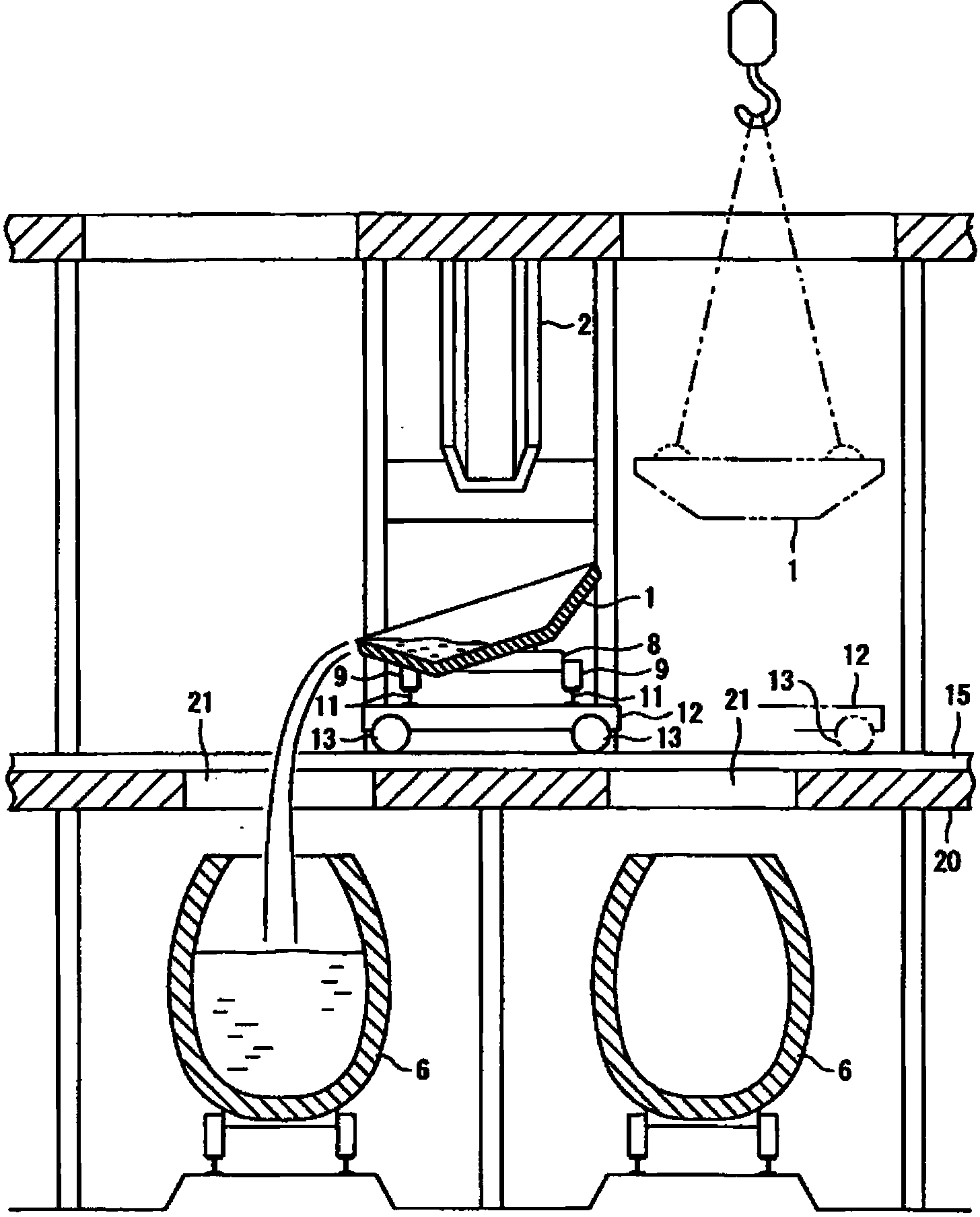
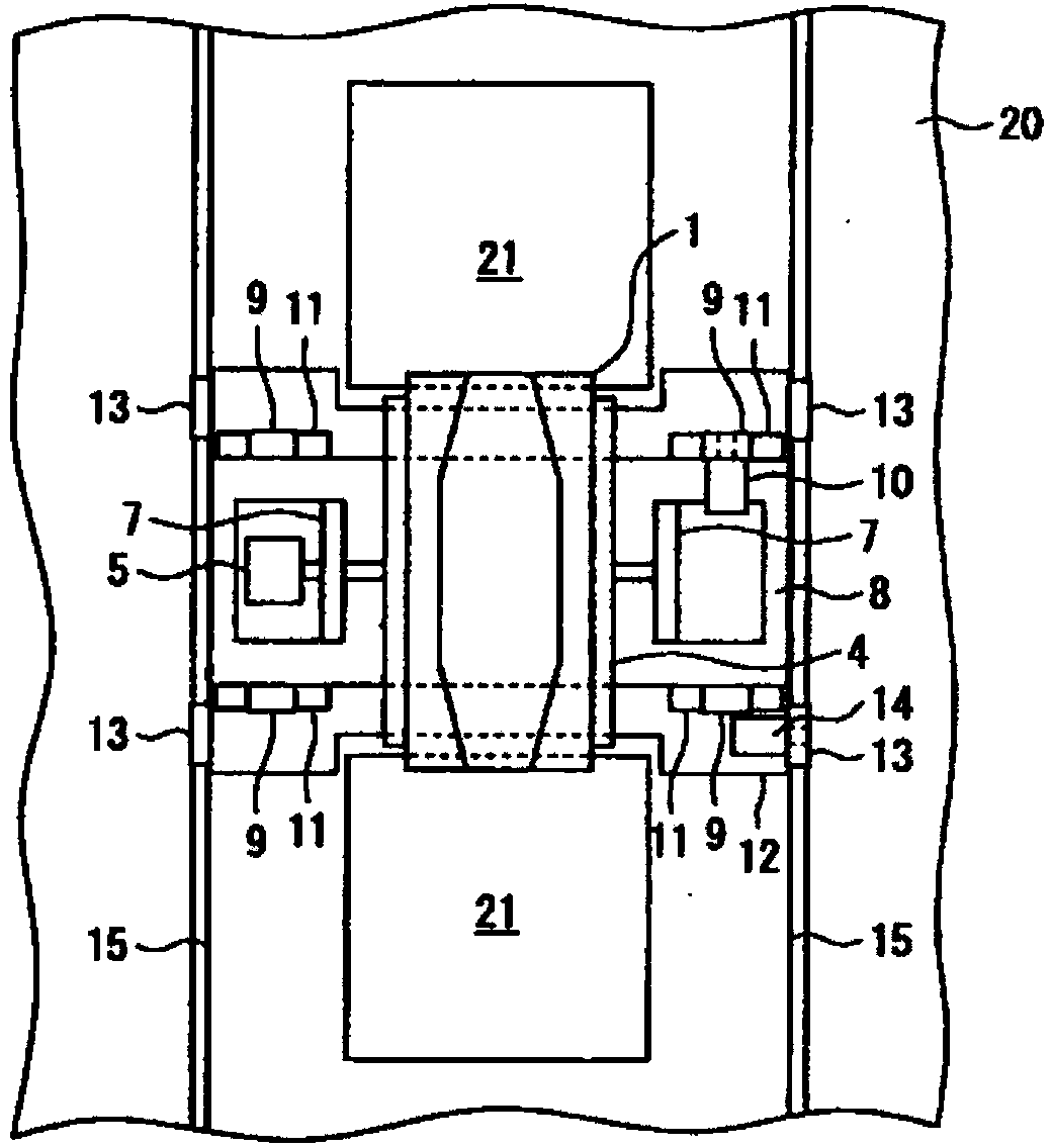
[0022] Next, an embodiment of the molten iron pouring trough facility of the present invention will be described with reference to the drawings.

[0023] Figure 1 to Figure 3 It is an overall view of the molten iron pouring trough equipment of this embodiment, figure 1 is the front view, figure 2 is a side view, image 3 is the floor plan. Symbol 1 in the figure is pouring ditch, and symbol 2 is tapping ditch. A metal frame 3 at the end of the iron trough is installed at the lower end of the tap trough 2 . In the figure, the molten iron flowing from the blast furnace is poured from the tapping trough 2 to the pouring trough 1 through the metal frame 3 at the end of the molten iron trough. The pouring channel 1 is supported by a support frame 4 which is rotated by using an electric motor 5, for example figure 2 Tilt in any of the clockwise and counterclockwise directions. Therefore, if figure 2 As shown, by tilting the pouring ditch 1 clockwise or counterclockwise, ...


PUM


Abstract

Provided is a tilting runner apparatus for molten iron whereby a tilting runner can be removed independently of the technique of a crane operator and without being damaged. Even in a case where two iron tapping runners (2) are disposed facing each other above a tilting runner (1), to adjust the pour position of molten iron from the iron tapping runners (2), the position of the tilting runner (1) can be moved in the longitudinal direction of the iron tapping runners (2) for each upper truck (8) by moving upper truck wheels (9) along narrow-gauge rails (11) of a lower truck (12). To remove the tilting runner (1), the position of the tilting runner (1) can be moved in the direction orthogonal to the longitudinal direction of the iron tapping runners for each lower truck by moving the wheels of the lower truck along floor rails. The tilting runner (1) can thereby be picked up without interfering with the iron tapping runners (2).

Description

technical field [0001] The present invention relates to hot metal tilting runner equipment for injecting hot metal flowing out of a blast furnace into a conveying vehicle, and is particularly suitable for facilitating the replacement work of a tilting runner. Background technique [0002] The molten iron flowing from the blast furnace is poured from the trough through the metal frame at the end of the molten iron trough to the pouring trough, and the pouring trough is tilted to be poured into a transport vehicle called a torpedo car. When the pouring ditch is removed due to replacement or repair of the pouring ditch, if the pouring ditch is lifted directly, it will interfere with the metal frame at the end of the iron gutter. Therefore, in the past, the metal frame at the end of the iron gutter was removed and then the pouring ditch was lifted by a crane. However, due to the complicated disassembly and assembly process of the metal frame at the end of the iron gutter, it was...

Claims


Application Information

Patent Timeline
Patent Type & Authority Applications(China)
IPC IPC(8): C21B7/14F27D3/14
CPCC21C5/5294C21C5/285F27D3/14Y02P10/20C21B7/14
Inventor 滨田亮安川明生
Owner JFE STEEL CORP
Why Eureka
Try Eureka