Yarn tension constant device

A technology of yarn tension and yarn guide hook, which is applied in the direction of textiles and papermaking, etc. It can solve the problems that the yarn tension cannot be precisely controlled, it is difficult to achieve constant tension, and the size of the tension cannot be adjusted, so as to achieve constant tension, constant torque, Exactly consistent yarn tension

Active Publication Date: 2013-11-20
AVIC SHAANXI HUAYAN AERO INSTR
View PDF12 Cites 5 Cited by
  • Summary
  • Abstract
  • Description
  • Claims
  • Application Information

AI Technical Summary

Problems solved by technology

The technical effect of the cam device is better than that of the torsion spring assembly, but it is difficult to achieve a constant tens

Method used


Image

  • Yarn tension constant device
  • Yarn tension constant device
  • Yarn tension constant device

Examples


Example Embodiment

[0021] The present invention will be further described below in conjunction with the embodiments and accompanying drawings.

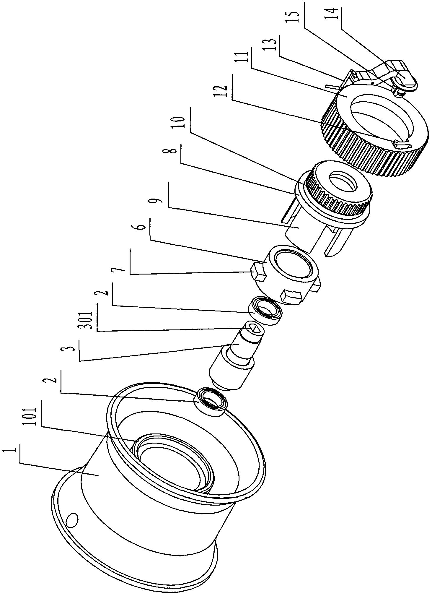
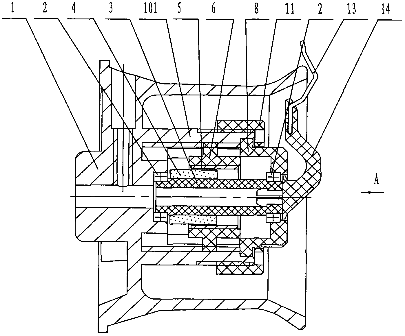
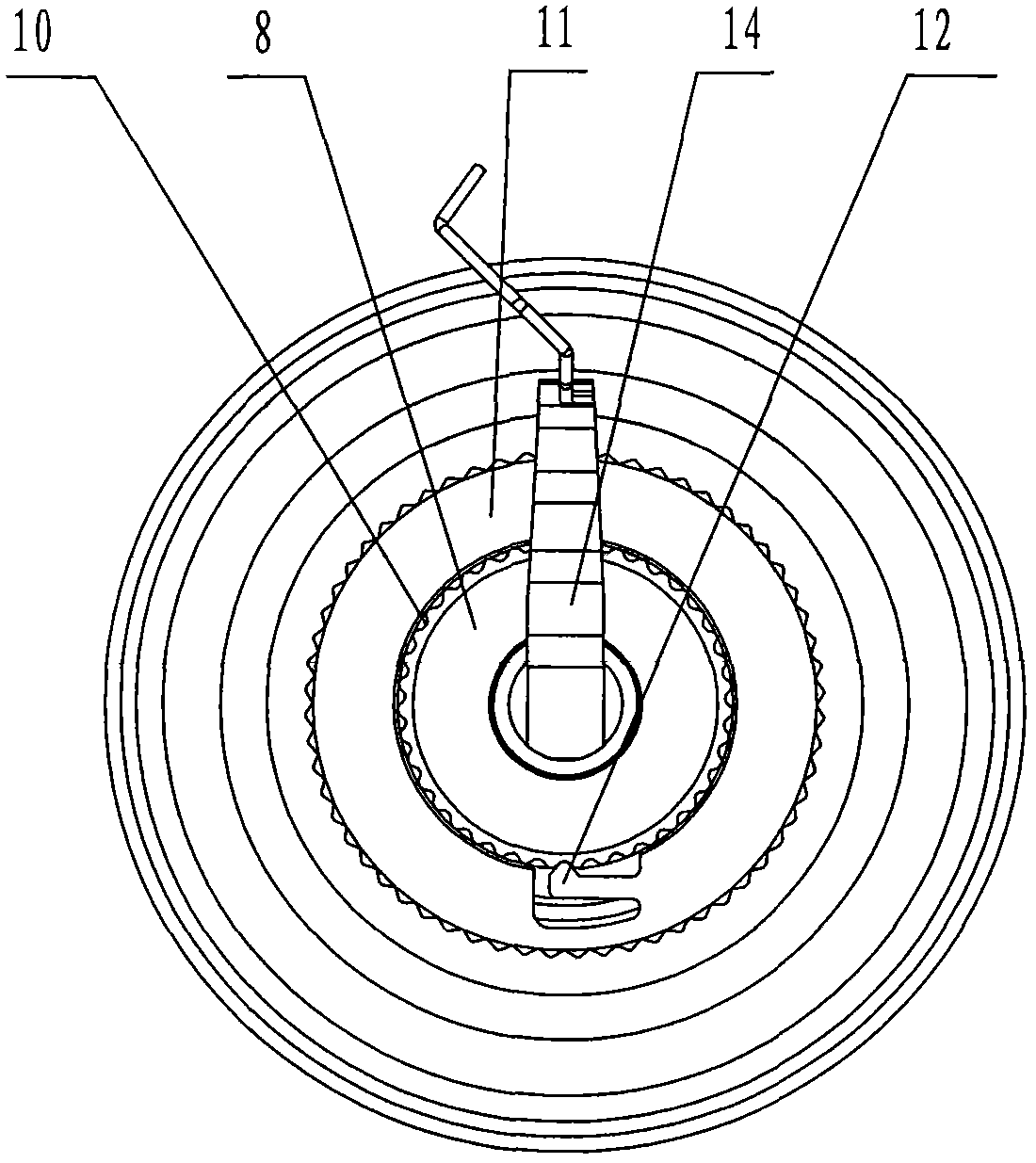
[0022] As shown in the figure, the present invention mainly consists of a roller 1, a mandrel 3, a magnetic sleeve 4, a hysteresis sleeve 5, a sleeve 6, an adjustment disc 8, an annular locking cover 11 and a guide hook 13. The bottom of the inner cavity of the roller 1 is fixedly provided with a cylinder bracket 101 coincident with its axis. The inner wall of the cylinder bracket 101 has internal threads, and the outer edge has external threads; there is a shaft hole on the adjustment disc 8; the mandrel 3 passes through the bearing 2 Installed in the cylindrical support 101, the rear end is located on the body of the roller 1 at the bottom of the inner cavity of the cylindrical support 101, the front end is located on the shaft hole of the adjustment disc 8, the mandrel 3 is driven by the motor; the magnetic sleeve 4 is fixed on the core On the rear s...


PUM


Abstract

The invention discloses a yarn tension constant device which mainly comprises a roller, a mandrel, a magnetic sleeve, a magnetic-lag sleeve, a sleeve base, an adjusting disc, an annular locking cover and a yarn guiding hook. A cylinder support which coincides with the axis of a roller inner cavity is fixedly arranged on the roller inner cavity. The mandrel is arranged in the cylinder support. The magnetic sleeve or the magnetic-lag sleeve is fixedly arranged on the back side surface of the mandrel in a sleeved mode. The magnetic sleeve or the magnetic-lag sleeve is fixed in the sleeve base which is arranged in the cylinder support in a rotating mode and enables the magnetic sleeve and the magnetic-lag sleeve to form partial sleeve connecting. An air gap is reserved between the two surfaces of the sleeve-connecting part. The adjusting disc is connected to the back face of the sleeve base in an inserting mode. The annular locking cover is arranged at an edge opening of the cylinder support in a rotating mode and abuts against the adjusting disc. The yarn guiding hook is arranged at the front end of the mandrel. According to the yarn tension constant device, torsion on the yarn guiding hook is generated by the corresponding magnetic sleeve and the corresponding magnetic-lag sleeve, the torsion is constant and can be adjusted accurately, and the roller can carry out storing and paying off on yarn properly according to the magnitude of tension of the yarn. The yarn tension constant device can guarantee the fact that yarn tension on forming cheese yarn is complete the same.

Description

technical field [0001] The invention belongs to the field of spinning machinery, and in particular relates to a device for keeping yarn tension constant during bobbin spinning. Background technique [0002] During the bobbin spinning process, the precise control of the yarn tension and keeping the yarn tension constant is a key technology related to the quality of the bobbin yarn, and it is also a technical difficulty of the spinning machine, especially the high-speed spinning machine. [0003] The yarn output speed of the spinning machine is constant, the rotation speed of the paper tube is constant when the yarn roll is formed, but the path of the yarn winding on the paper tube and the linear speed when it is wound at different positions of the paper tube are different. Constant changes, resulting in constant changes in yarn tension, especially in the spinning of cone yarns. In order to obtain a well-formed package, the tension of the yarn must first be adjusted precisely...

Claims


Application Information

Patent Timeline
IPC IPC(8): D01H13/10
Inventor 樊宝军胡革明付小军张娥
Owner AVIC SHAANXI HUAYAN AERO INSTR
Why Eureka
Try Eureka