Miniature hydrodynamic piezoelectric switch valve

A piezoelectric switch and micro-fluid technology, applied in valve details, valve devices, valve operation/release devices, etc., can solve the problems of high flatness and assembly accuracy of piezoelectric wafers, unsatisfactory cut-off and flow capabilities, Problems such as large surface tension and resilience, etc., to achieve the effect of flexible installation, good cut-off performance, and high cut-off pressure

Inactive Publication Date: 2013-11-20
刘勇
View PDF6 Cites 9 Cited by
  • Summary
  • Abstract
  • Description
  • Claims
  • Application Information

AI Technical Summary

Problems solved by technology

Using the piezoelectric chip to directly control the opening and closing of the valve hole can make the structure of the piezoelectric valve more compact and easy to realize miniaturization. However, due to the small deformation of the piezoelectric chip, only the local deformation of the piezoelectric chip is used in the working process. Therefore, the requirements for the flatness and assembly accuracy of the piezoelectric wafer are relatively high, which increases the manufacturing cost.
In order to obtain a large deformation, piezoelectric stacks are usually used to construct piezoelectric valves, supplemented by a displacement amplification mechanism, but the thickness is not easy to reduce, which is not conducive to miniaturization
Some scholars have also proposed that the piezoelectric valve of the hydraulic membrane displacement amplifying mechanism can compress the volume of the displacement amplifying mechanism to the minimum. However, due to the large surface tension and resilience of the plane membrane used, the valve's cut-off and flow Unsatisfactory ability

Method used


Image

  • Miniature hydrodynamic piezoelectric switch valve
  • Miniature hydrodynamic piezoelectric switch valve
  • Miniature hydrodynamic piezoelectric switch valve

Examples


Embodiment 1

[0031] Embodiment 1, please refer to Figure 4 Shown:

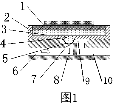
[0032] The piezoelectric driving part of a miniature hydraulic piezoelectric switch valve is composed of a piezoelectric vibrator 1, a liquid storage chamber 2, a driving liquid 3, a driving hole 4 and a flexible valve plug 5, wherein the piezoelectric vibrator 1 is set in the liquid storage chamber On the upper part of 2, the wall on the right side of the liquid storage chamber 2 is provided with a driving hole 4 communicating with the inner cavity of the liquid storage chamber 2, and a flexible valve plug 5 is arranged on the driving hole 4. The piezoelectric vibrator 1, the liquid storage chamber 2 It forms a sealed space together with the flexible valve plug 5, and the inside is filled with the driving fluid 3, and the flexible valve plug 5 is a bellows-shaped structure.

Embodiment 2

[0033] Embodiment two, please refer to Figure 5 Shown:

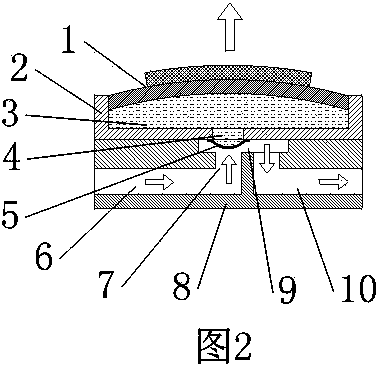
[0034] The piezoelectric driving part of a miniature hydraulic piezoelectric switch valve is composed of a piezoelectric vibrator 1, a liquid storage chamber 2, a driving liquid 3, a driving hole 4 and a flexible valve plug 5, wherein the piezoelectric vibrator 1 is provided with two, They are arranged at the upper and lower parts of the liquid storage chamber 2 respectively. The drive hole 4 communicating with the inner cavity of the liquid storage chamber 2 is opened on the wall of the right side of the liquid storage chamber 2. The flexible valve plug 5 is arranged on the drive hole 4. The electric vibrator 1, the liquid storage chamber 2 and the flexible valve plug 5 together form a sealed space, which is filled with the driving fluid 3, and the flexible valve plug 5 is a bellows-shaped structure.

Embodiment 3

[0035] Embodiment three, please refer to Image 6 Shown:

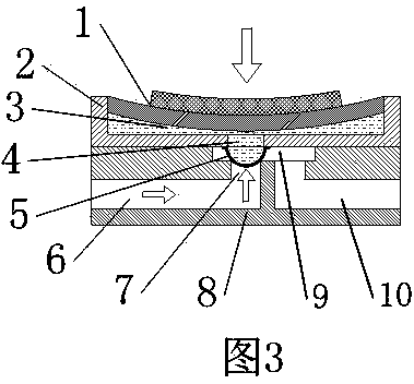
[0036] The piezoelectric driving part of a miniature hydraulic piezoelectric switch valve is composed of a piezoelectric vibrator 1, a liquid storage chamber 2, a driving liquid 3, a driving hole 4 and a flexible valve plug 5. There are two liquid storage chambers 2, the upper and lower Superposed arrangement, the inner cavities of the two liquid storage chambers 2 are connected, and there are two piezoelectric vibrators 1, one of which is set on the upper part of the upper liquid storage chamber 2, and the other piezoelectric vibrator 1 is set on the lower part of the liquid storage chamber 2. In the lower part, the bottom of the upper liquid storage chamber 2 is provided with a driving hole 4 communicating with the inner cavity of the liquid storage chamber 2, and a flexible valve plug 5 is arranged on the driving hole 4, and the piezoelectric vibrator 1, the liquid storage chamber 2 and the flexible valve plug 5 To...


PUM


Abstract

The invention relates to a miniature hydrodynamic piezoelectric switch valve which comprises a piezoelectric oscillator, a liquid storage cavity, a driving hole, a flexible valve plug, a valve opening, an inlet, an outlet, a flow passage and driving liquid, wherein the piezoelectric oscillator is arranged at the upper part or the lower part of the liquid storage cavity; the driving hole connected with the liquid storage cavity is formed in the upper part, the lower part or the cavity wall of the liquid storage cavity; the flexible valve plug is arranged on the driving hole and matched with the valve opening; the piezoelectric oscillator, the liquid storage cavity and the flexible valve plug together form a sealed space filled with the driving liquid. The switch valve provided by the invention controls the opening and closing of a valve indirectly by virtue of hydraulic power, can fully utilize the overall deformation of a piezoelectric chip, and has the advantages of high response speed, good cut-off property, high cut-off pressure, low leakage rate and easiness in processing and manufacturing. The piezoelectric driving part and the fluid control part of the switch valve can be separated through a liquid guide tube, and the mounting form is flexible.

Description

technical field [0001] The invention relates to a switch valve, in particular to a miniature hydraulic piezoelectric switch valve. Background technique [0002] At present, microvalve is a key component in microfluidic control system, and it can be divided into passive valve and active valve according to the presence or absence of driving source. Passive valves are one-way valves that can only conduct in one direction, and are not suitable for occasions that require two-way flow and cut-off. The active valve has unique advantages because it can actively control the opening and closing of the valve and can be closed in both directions. There are many types of miniature active valves, which can be divided into piezoelectric valves, thermal valves, electrostatic valves, solenoid valves, memory alloy valves, etc. according to different driving methods. Piezoelectric valves have been disclosed in many design schemes, such as CN 101755157A, CN 1391639A, CN 1354335A, CN 101573548...

Claims


Application Information

Patent Timeline
Patent Type & Authority Applications(China)
IPC IPC(8): F16K31/02F16K31/12
Inventor 刘勇杨志刚陈松王建涛吴越沈燕虎
Owner 刘勇
Why Eureka
Try Eureka