Waterproof projection lamp

A technology for floodlights and lamp housings, applied in the field of lighting, can solve problems such as unreliable waterproof sealing performance, potential safety hazards, affecting electrical circuits, etc. Effect

Active Publication Date: 2013-11-20
浙江中睿低碳科技有限公司
View PDF6 Cites 2 Cited by
  • Summary
  • Abstract
  • Description
  • Claims
  • Application Information

AI Technical Summary

Problems solved by technology

The light-transmitting glass on the surface of the existing lamps is an independent structure with the flange, and is sealed and connected with each other through a rubber ring. The rubber ring is used outdoors and is easy to age. The waterproof and sealing performance is not reliable, which affects the electrical circuit and poses a safety hazard.

Method used


Image

  • Waterproof projection lamp
  • Waterproof projection lamp
  • Waterproof projection lamp

Examples


Embodiment 1)

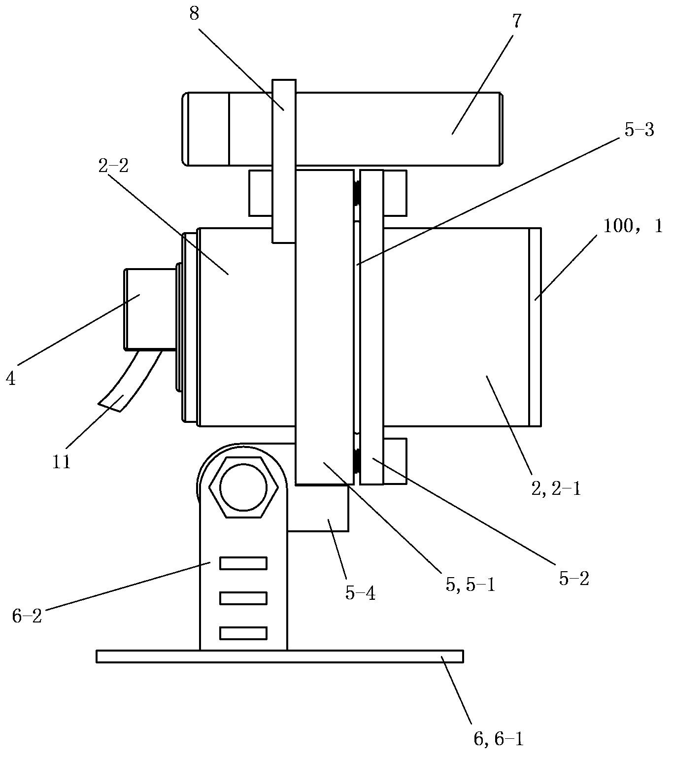
[0043] See figure 1 with Image 6 , The waterproof floodlight of the present invention includes a lamp body 100 , a connecting assembly 5 , a bracket 6 , a laser emitter 7 and a connecting frame 8 .

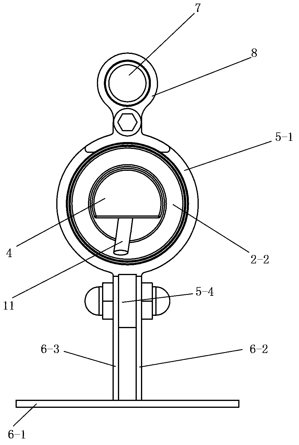
[0044] See figure 1 with Image 6 , the lamp body 100 includes a lampshade 1 , a lamp housing 2 , a wiring cap 4 , an LED lamp board 9 , a lens assembly 10 and a power cord 11 .

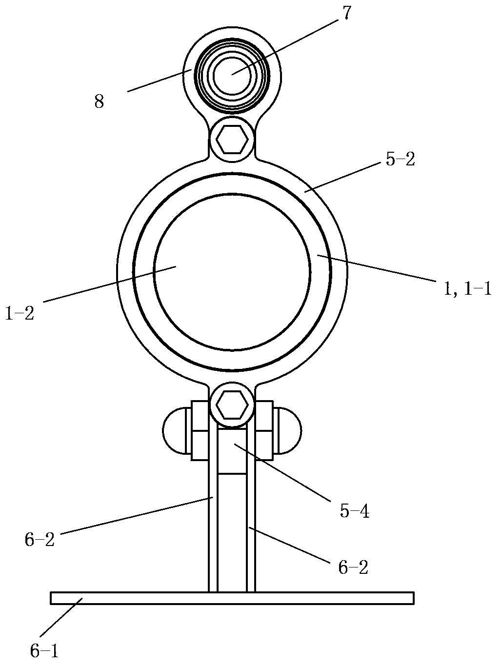
[0045] See figure 2 , Figure 5 with Image 6 , The lampshade 1 includes a stainless steel flange 1-1 and a glass 1-2 made of stainless steel. The stainless steel flange 1-1 of this embodiment adopts 316 stainless steel. The glass 1-2 is airtight and fixedly arranged in the stainless steel flange 1-1. When making, first process the glass into the shape and size corresponding to the stainless steel flange, then put it into the stainless steel flange, and place it in the corresponding graphite mold together, and then enter the electric furnace oven for heating, using nitrogen gas Protection, at ...

Embodiment 2)

[0057] See Figure 9 with Figure 10 , the rest of this embodiment is the same as that of Embodiment 1, except that the connection assembly 5 includes a first connection ring 5-1 and an adjustment plate 5-4.

[0058] The stainless steel sealing plate 4-1 of the wiring cap 4 is provided with a circular through hole 4-1-1. The glue filling part 4-2 is a cylindrical shell-shaped part with an opening facing to the right made of stainless steel, and its shape corresponds to the circular through hole 4-1-1. The left side of the glue filling part 4-2 is provided with a wire hole 4-2-1 running through it. The glue potting part 4-2 is laser welded from left to right, sealed and fixedly connected to the circular through hole 4-1-1 of the stainless steel sealing plate 4-1.

[0059] The first connecting ring 5-1 is an integral piece made of steel, and the upper part of the outer circumference of the first connecting ring 5-1 is provided with a radially outward protruding part, and the ...

Embodiment 3)

[0062] This embodiment is the same as Embodiment 1, and the difference is that the lamp housing 2 of this embodiment is one piece, without the front lamp housing 2-1, and the left and right length of the original rear lamp housing 2-2 is extended It is the sum of the left and right lengths of the original front lamp housing 2-1 and the rear lamp housing 2-2.


PUM


Abstract

The invention discloses a waterproof projection lamp which comprises a lamp body, a connecting assembly and a support. The lamp body is fixedly arranged on the support through the connecting assembly. The waterproof projection lamp is characterized in that the lamp body comprises a lampshade, a lamp shell, a wiring cap, an LED lamp board, a lens component and a power line. The lampshade comprises a stainless steel flange and glass. The wiring cap, the lamp shell and the stainless steel flange of the lampshade are sequentially and mutually and fixedly connected in a laser welding and sealed mode. The LED lamp board and the lens assembly are sequentially and fixedly arranged in the lamp shell from left to right. One end of the power line is electrically connected with a corresponding electrode of the LED lamp board and the other end of the power line is located outside the wiring cap. The wiring cap is filled with pouring sealant so that sealing waterproof processing can be conducted. The portion, located in the wiring cap, of the power line is coated with the pouring sealant in a sealed and waterproof mode.

Description

technical field [0001] The invention relates to the technical field of lighting, in particular to a waterproof floodlight. Background technique [0002] Flood lights make the illuminance on the designated illuminated surface higher than that of the surrounding environment. Generally, it can aim in the required direction and requires a structure that is not affected by climatic conditions. It is mainly used for large-area operation sites, mines, building outlines, stadiums, overpasses, parks and flower beds, etc. Therefore, almost all outdoor use Large-area lighting fixtures can be regarded as floodlights. The output beam angle of the floodlight is wide or narrow, and the range of variation is between 5° and 110°. At present, more and more cities have begun to install corresponding floodlights for night lighting in blocks with relatively concentrated high-rise buildings, bustling commercial districts, or urban landmark buildings, which play a role in lighting and beautifyin...

Claims


Application Information

Patent Timeline
Patent Type & Authority Applications(China)
IPC IPC(8): F21S8/00F21V31/04F21V17/10F21V21/14F21Y101/02
CPCF21S8/00F21S8/08F21V3/00F21V3/02F21V15/01F21V17/101F21V17/12F21V19/001F21V21/14F21V23/00F21V23/06F21V31/00F21V31/04F21W2131/10
Inventor 黄俊
Owner 浙江中睿低碳科技有限公司
Why Eureka
Try Eureka