Waste heat utilization system for aluminium melting furnace
A technology of aluminum melting furnace and waste heat, which is applied in furnaces, waste heat treatment, furnace components, etc., can solve problems such as waste of heat energy, achieve the effects of reducing emission pollution, compact structure, and improving heat recovery efficiency
- Summary
- Abstract
- Description
- Claims
- Application Information
AI Technical Summary
Problems solved by technology
Method used
Image

Examples
Embodiment approach
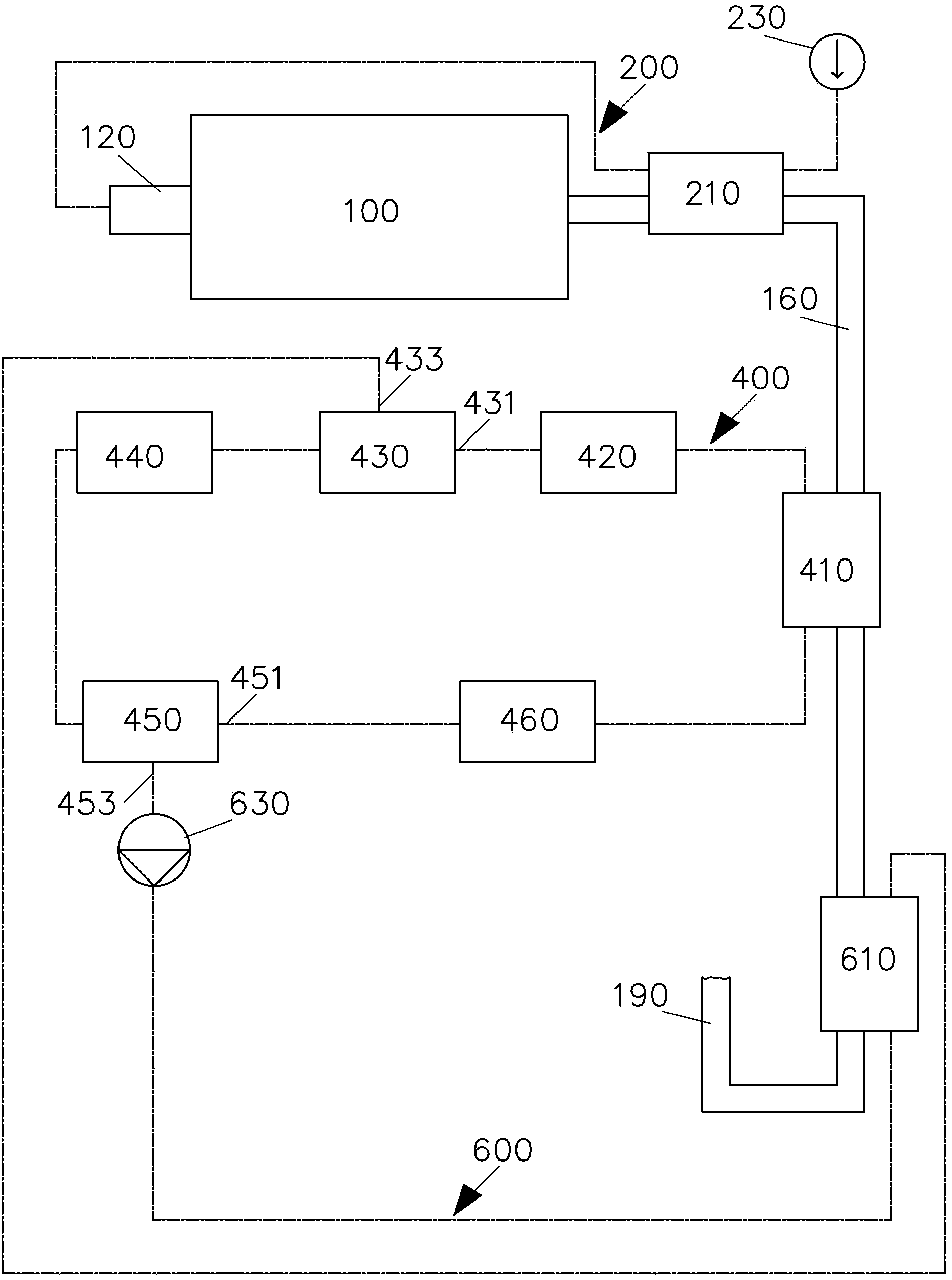
[0031] Please refer to figure 1 According to an embodiment of the present invention, the aluminum melting furnace waste heat utilization system includes a furnace body 100, a nozzle 120, a flue gas pipe 160, a first-stage waste heat utilization system 200, a second-stage waste heat utilization system 400, and a third-stage waste heat utilization system. System 600.
[0032] A furnace (not shown) is disposed inside the furnace body 100 . The nozzle 120 is disposed on one end wall of the furnace body 100 . The flue gas pipe 160 is connected to the other end wall of the furnace body 100 to discharge the flue gas generated in the furnace to the chimney 190 .
[0033]The first-stage waste heat utilization system 200 includes a high-temperature heat exchanger 210 arranged upstream of the flue gas pipeline 160. The high-temperature heat exchanger 210 has a flue gas flow path (not shown) and a fluid flow path (not shown), And the first-stage waste heat utilization system 200 also i...
PUM
 Abstract
Description
Claims
Application Information
 - R&D
- Intellectual Property
- Life Sciences
- Materials
- Tech Scout
- Unparalleled Data Quality
- Higher Quality Content
- 60% Fewer Hallucinations
Browse by: Latest US Patents, China's latest patents, Technical Efficacy Thesaurus, Application Domain, Technology Topic, Popular Technical Reports.
© 2025 PatSnap. All rights reserved.Legal|Privacy policy|Modern Slavery Act Transparency Statement|Sitemap|About US| Contact US: help@patsnap.com