
Spiral array cold cathode X-ray tube with large emission area field emission composite material

A composite material and emission area technology, applied in the directions of X-ray tube electrodes, X-ray tube components, etc., can solve the problem of poor consistency of the sharp cone array, poor consistency of large-area cathodes, and small-area cathodes that cannot meet the needs of high-dose X-rays and other problems, to achieve the effect of resistance to ion bombardment, good chemical stability, and improved stability and life.

Active Publication Date: 2016-08-10
CHENGDU CHUANGYUAN ELECTRONICS
View PDF4 Cites 0 Cited by
  • Summary
  • Abstract
  • Description
  • Claims
  • Application Information

AI Technical Summary

Problems solved by technology

[0013] In order to overcome the technical defects that the small-area cathode of the field emission tube in the prior art cannot meet the needs of large-dose X-rays and the consistency of the large-area cathode is poor, the present invention discloses a cone array cold cathode X with a large emission area field emission composite material. light pipe
[0015] The cone-array cold-cathode X-ray tube with a field emission composite material with a large emission area described in the present invention overcomes the problem that the central point of the array is consistent with the cone array at the edge when a single-chip large-area cathode cone array is prepared at one time. The problem of poor performance, while meeting the requirements of the X-ray tube for the emission current when the X-ray dose is output; high-quality X-ray imaging can be obtained

Method used


Image

  • Spiral array cold cathode X-ray tube with large emission area field emission composite material
  • Spiral array cold cathode X-ray tube with large emission area field emission composite material
  • Spiral array cold cathode X-ray tube with large emission area field emission composite material

Examples


Embodiment Construction

[0032] The specific embodiment of the present invention will be further described in detail below in conjunction with the accompanying drawings.

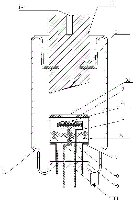
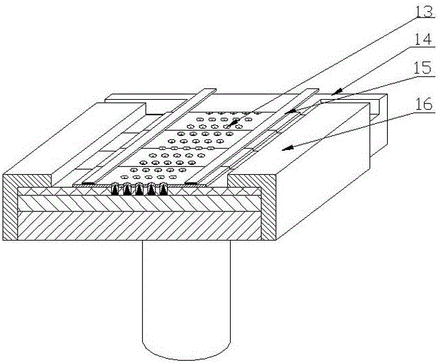
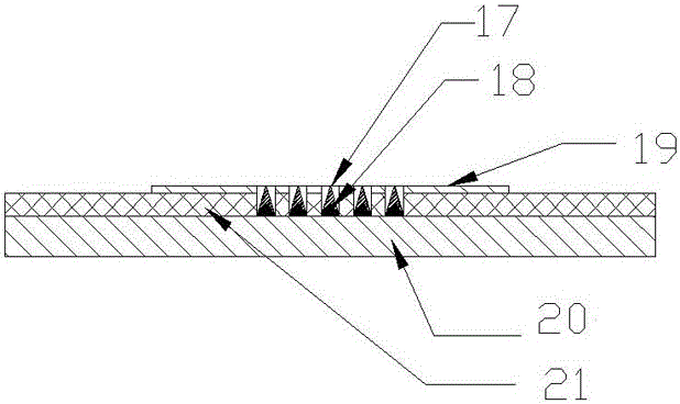
[0033] The pointed cone array cold cathode X-ray tube with a large emission area field emission composite material according to the present invention includes a cathode part; The sheet includes a base, an inner grid sheet, and a plurality of sub-cathodes arranged in an array on the base. grid hole; there is an insulating layer between the base and the inner grid sheet; the cathode component also includes an electrical connection compression structure for fixing a plurality of pointed cone array cold cathode sheets and having lead-out electrodes.

[0034] Such as Figures 2 to 3 A specific embodiment of the cathode part is shown. The cathode part is continuously spliced ​​by 4 rectangular-shaped pointed cone array cold cathode sheets. The inner grid sheet above the cathode is composed of a plurality of inner grid holes, and each su...


PUM


Abstract

The invention relates to a pointed cone array cold cathode X light tube with large-emitting-area field emission composite materials. A cathode component comprises a plurality of pointed cone array cold cathode sheets in continuous splicing joint, a pointed cone array cold cathode comprises a base, an inner grid electrode sheet and a plurality of sub cathodes, the sub cathodes are distributed on the base and are in array-shaped arrangement, the inner grid electrode sheet is positioned above the sub cathodes, the center of the inner grid electrode sheet is provided with inner grid electrode holes in one-to-one correspondence to the positions of the sub pointed cone array cold cathodes, an insulating layer is also arranged between the base and the inner grid electrode sheet, and the cathode component also comprises an electric connection compressing structure which is used for fixing the pointed cone array cold cathode sheets and leading out the electrodes. The pointed cone array cold cathode X light tube has the advantages that the problem of poor consistency of pointed cone arrays at array center point and edge parts during the one-step preparation of single-sheet large-area cathode pointed cone arrays is solved, meanwhile, the requirement of the X light tube on the emitting current during great X dosage output is met, and high-quality X light imaging is obtained.

Description

technical field [0001] The invention belongs to the field of physical electronics and relates to a cone-array cold-cathode X-ray tube with a field emission composite material with a large emission area. Background technique [0002] Various X-ray equipment involved in medical treatment, medical diagnosis, industrial inspection, and safety technology require high-performance X-ray tubes. As one of the core components of X-ray imaging equipment, X-ray tubes should have the characteristics of good imaging quality, stable and reliable operation, and long service life. The demand is becoming more and more prominent. [0003] The existing X-ray tubes mainly have the following problems: [0004] 1. The traditional CT tube uses a composite material rotating anode target, which is large in size and complex in structure; high in cost. 2. Most of the existing X-ray tubes use the traditional single-helix tungsten wire cathode, which has a high work function (4.52eV), and the cathode ...

Claims


Application Information

Patent Timeline
Patent Type & Authority Patents(China)
IPC IPC(8): H01J35/06H01J35/04
Inventor 林祖伦徐如祥于海波代秋生曹贵川王小菊祁康成
Owner CHENGDU CHUANGYUAN ELECTRONICS
Learn More