Uv-led ionization source and process for low energy photoemission ionization

a low-energy photoemission and ionization technology, applied in the field of ionization sources and systems, can solve the problems of inability of uv-leds to directly photo-ionize organic or atmospheric components, and insufficient light from a uv led, so as to reduce the complexity and cost of ion sources, reduce pressure, and the effect of robust uv-led sources

Active Publication Date: 2012-10-04
BATTELLE MEMORIAL INST
View PDF4 Cites 15 Cited by
  • Summary
  • Abstract
  • Description
  • Claims
  • Application Information

AI Technical Summary

Benefits of technology

[0045]The UV-LED photoemission ionization source (see FIG. 1) and process (see FIG. 2) of the invention solve known problems in the prior art for detection of organic species and surface residues. The unique ability of the present invention to generate small photocurrents in certain metals and other conducting surfaces provides attractive features. The present invention with its low-power, scalable UV-LED ionization source may be integrated into next generation, compact mass spectrometers to create ultra compact, hand-held gas analyzers. Benefits are numerous. First, the complexity and cost of the ion source are substantially reduced. Second, the UV-LED source is robust compared with conventional lamps, lasers, and electron filaments. The UV-LED ionization source of the invention provides UV light of a sufficient energy to ionize many diverse analytes, generating ions of organic vapors that provide for detection without the need of high-energy potential fields or low pressure vacuum systems. For example, conventional El sources must operate at a reduced pressure due to requirements of the high temperature, delicate electron filament. Since the sensitivity of these El instruments is proportional to the number of ions generated within the sampled gas, ionization occurs at a reduced pressure, which severely limits the maximum sensitivity of these instruments. Third, the ion source of the invention requires few if any additional electric fields within the ion source device. Fourth, the present invention easily generates ions at atmospheric pressure, which can increase ion intensity and reduce size of the device. As described herein, use of a conducting surface that has a sufficiently low work function (e.g., <4.4 eV for 280 nm UV light) can be used as a source of photoemission electrons. Modifying the surface (e.g., via oxidation or organic film deposition) can further lower the work function, which increase the types of conductive surfaces available as a photoemissive surface. Selecting higher-energy UV-LEDs can also extend the range of material selections for photoemissive surfaces. The UV-LED ionization depends on the photon energy of the light and the light source used. Fourth, the present invention provides a greater potential analyte density compared to low-pressure ion sources, as the maximum analyte density, e.g., at one (1) atmosphere, is significantly greater than that at a reduced pressure.
[0046]The following examples provide a further understanding of the invention in one or more aspects.

Problems solved by technology

With photons that have an energy of between 4 eV to 5 eV per, current UV LEDs lack the ability to directly photo-ionize organic or atmospheric components.
In addition, the light from a UV LED has both insufficient energy, for SPI to occur (most organic molecules ionize at >8 eV) and a photon flux that is too low for MPI or REMPI to occur.
Thus, currently available UV-LEDs are incapable of generating ions via SPI, MPI, or REMPI.

Method used


Image

  • Uv-led ionization source and process for low energy photoemission ionization
  • Uv-led ionization source and process for low energy photoemission ionization
  • Uv-led ionization source and process for low energy photoemission ionization

Examples


example 1

Background Tests

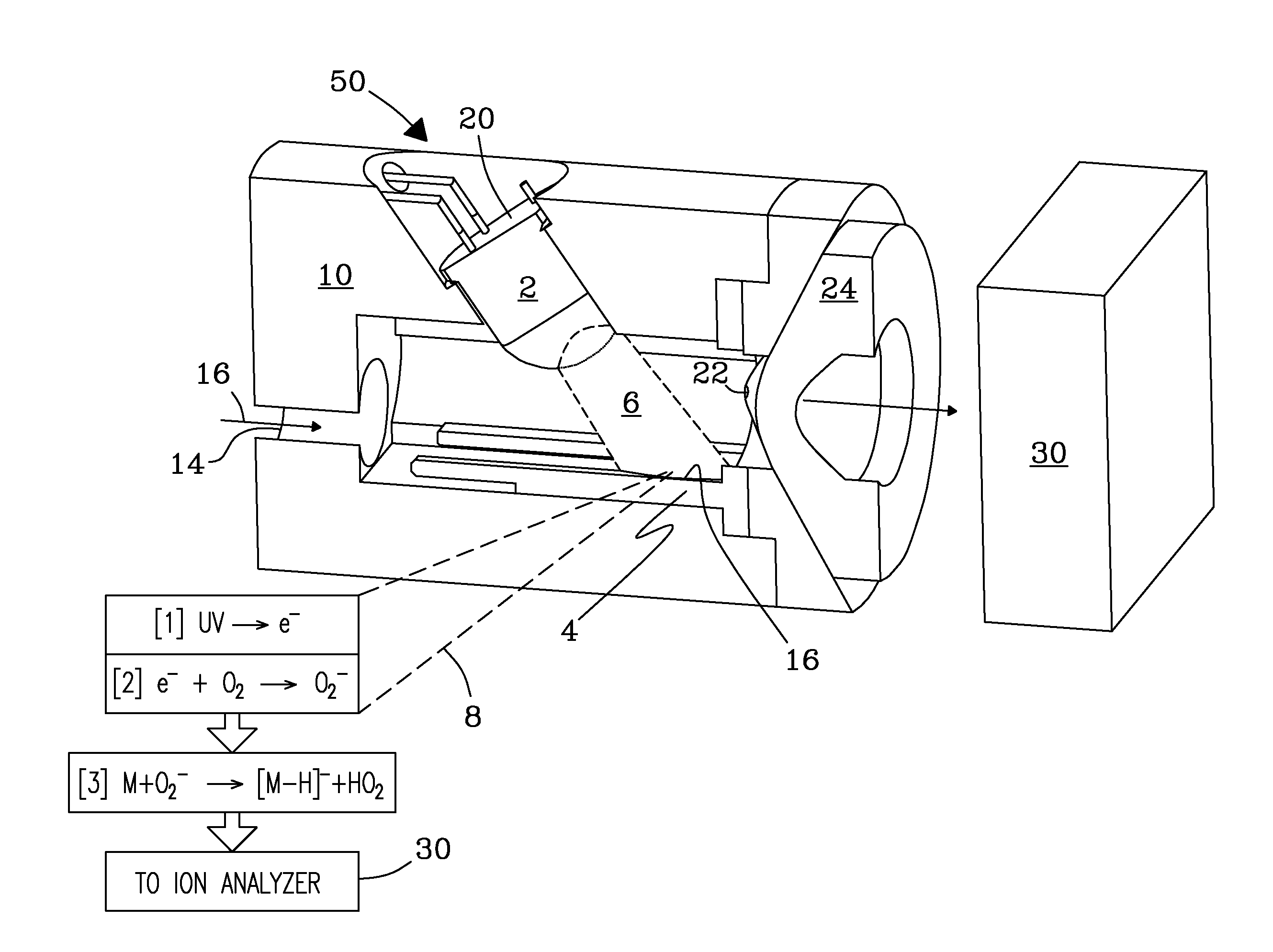
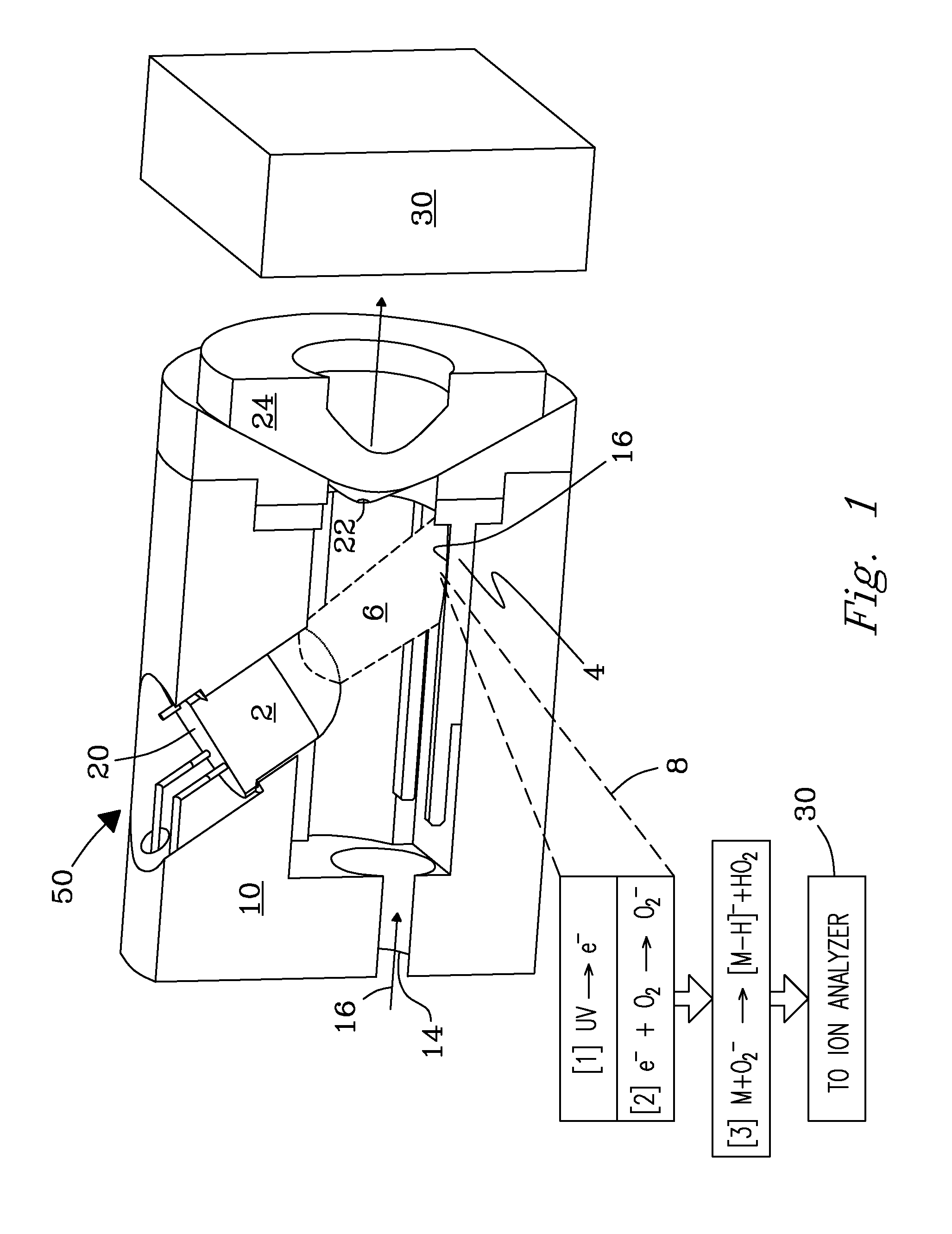
[0047]Ambient air was analyzed using a UV-LED source (FIG. 1) with the UV-LED “on” or “off” that involves monitoring and sampling of negative ions. A mass analyzer (MS) was set to monitor total ion count (TIC) from m / z 10 to m / z 400. UV-LED source was switched “on” by shining UV light onto a metal foil positioned, e.g., 0.5 cm from MS inlet, or “off”. A voltage of −500V was applied to the selected metal foil, and a voltage of −10V was applied to the cone surface.

example 2

Background Ions from Oxidized Aluminum Conducting Surface

[0048]In one test, background ions were generated in air at ambient temperature using a single UV-LED illuminating the conducting surface composed of oxidized aluminum. A background ion mixture resulting from UV light (280 nm) from a UV-LED source striking the conducting surface located near the sample cone was determined with an API 5000 atmospheric-sampling mass analyzer situated adjacent to UV-LED source. The sample cone was set to a potential of −7V. UV light from the UV-LED was set to strike the sample cone ˜0.5 cm from the MS inlet. The oxidized surface with the thin oxide film substantially lowered the work function of the material to 4.0 eV (compared to 4.23 eV for a non-oxidized aluminum), which occurs naturally at atmospheric pressure in room air. Work function for generation of photoelectrons on the non-oxidized surface is at the minimum necessary value to permit photoemission generation when exposed to 280 nm UV li...

example 3

Background Ions from Stainless Steel Conducting Surface

[0049]In another test, background ions were generated in sufficient quantity in air when a single UV-LED illuminated a conducting surface made of oxidized stainless steel at ambient temperature. Background ion mixture resulting from UV light (280 nm) from a UV-LED source striking a conducting surface located near a sample cone was determined with an API 5000 atmospheric-sampling mass analyzer situated adjacent to UV-LED source. Background ion mixture resulting from UV light (280 nm) striking a stainless steel metal surface was determined using an API 5000 atmospheric-sampling mass analyzer coupled to the UV-LED source. The sample cone was set to a potential of −7V. UV light from the UV-LED was set to strike the sample cone −0.5 cm from the MS inlet. UV light from UV-LED source was set to strike the sample cone just below the inlet to the mass analyzer. The stainless steel metal surface has a work function that is just sufficient...


PUM


Abstract

A UV-LED photoemission ionization source and process are disclosed that provide ionization of analytes including volatile molecular species and organic residues for detection with various ion analyzers. The UV-LED source produces low-energy UV light (200 nm to 400 nm) that yields photoemission electrons from various conducting surfaces. These photoemission electrons provide direct and indirect ionization of analytes including trace organic residues without need of high electric fields.

Description

FIELD OF THE INVENTION[0001]The present invention relates generally to ionization sources and systems. More particularly, the invention relates to a UV-LED ionization device that includes a UV-LED ionization source and process that produces photoemission electrons for indirect or direct ionization of analytes.BACKGROUND OF THE INVENTION[0002]Attention in the scientific community has avoided exploring LEDs as a viable light source because of their low light intensity (i.e., photon flux) or low photon energy. UV LEDs in the region of 240 nm to 280 nm are now becoming commercially available, although their flux is still limited. Traditional photon-based ion sources have either very high photon energies (e.g., Vacuum UV or VUV lamps and lasers) resulting in direct photo-ionization via Single Photon Ionization (SPI) or via a high intensity or focused laser beam(s), resulting in Multi-Photon Ionization (MPI) or Resonance-Enhanced Multi-Photon Ionization (REMPI). Other UV-laser techniques ...

Claims


Application Information

Patent Timeline
Patent Type & Authority Applications(United States)
IPC IPC(8): H01J27/24H01J49/16
CPCH01J49/147H01J49/162
Inventor SHORT, LUKE C.BARINAGA, CHARLES J.EWING, ROBERT G.
Owner BATTELLE MEMORIAL INST
Why Eureka
Try Eureka