Control system and method for permanent magnet synchronous electric spindle driving

A technology of permanent magnet synchronization and drive control, applied in the control system, vector control system, motor generator control, etc., can solve the problem of low accuracy of rotor position estimation and achieve the effect of improving operating performance

Active Publication Date: 2013-11-20
GOOGOL TECH SHENZHEN LTD GUANGDONG
View PDF4 Cites 20 Cited by
  • Summary
  • Abstract
  • Description
  • Claims
  • Application Information

AI Technical Summary

Problems solved by technology

[0004] Based on this, it is necessary to provide a permanent magnet synchronous motorized spindle drive control system that ca

Method used


Image

  • Control system and method for permanent magnet synchronous electric spindle driving
  • Control system and method for permanent magnet synchronous electric spindle driving
  • Control system and method for permanent magnet synchronous electric spindle driving

Examples


Embodiment Construction

[0030] In order to make the object, technical solution and advantages of the present invention clearer, the present invention will be further described in detail below in conjunction with the accompanying drawings and embodiments. It should be understood that the specific embodiments described here are only used to explain the present invention, not to limit the present invention.

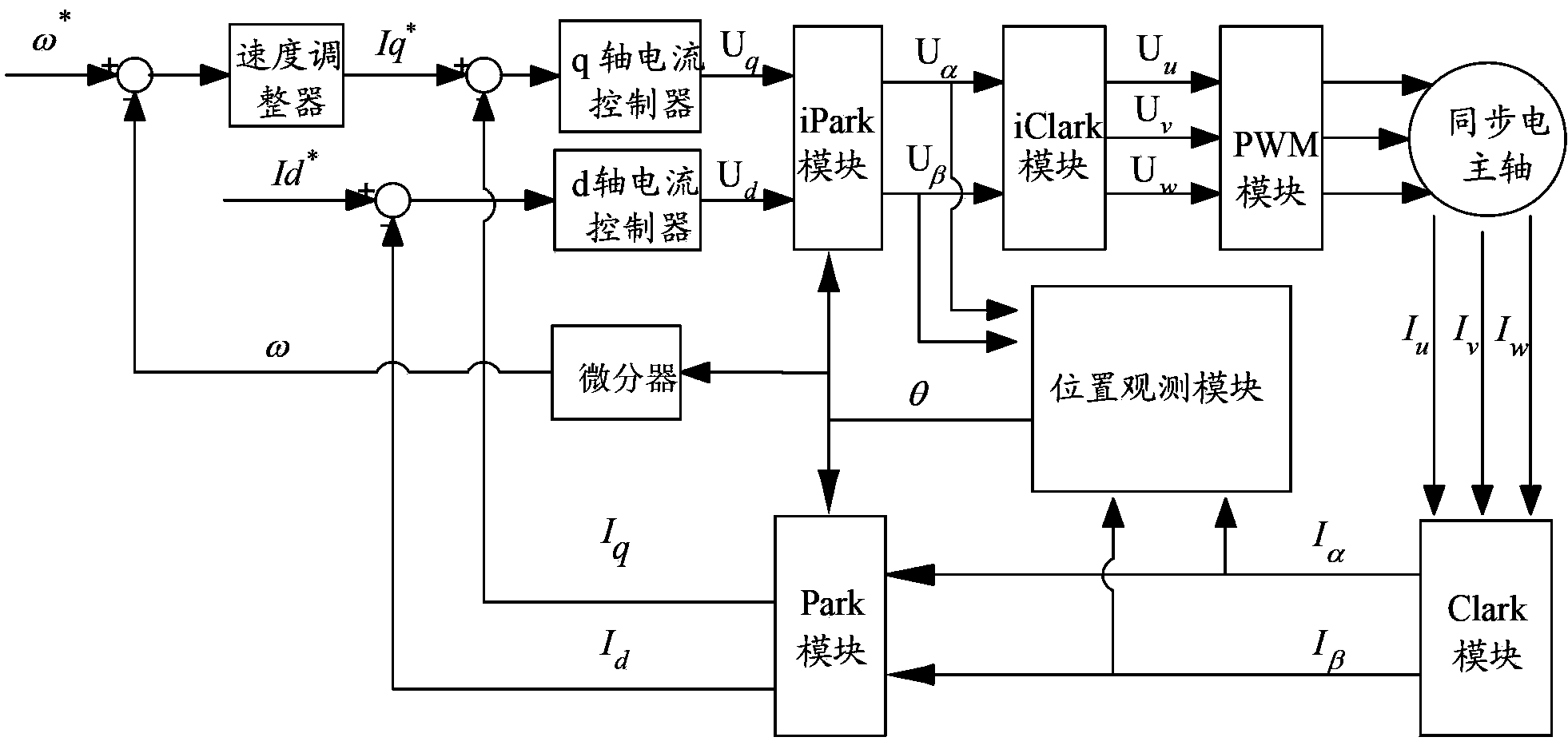
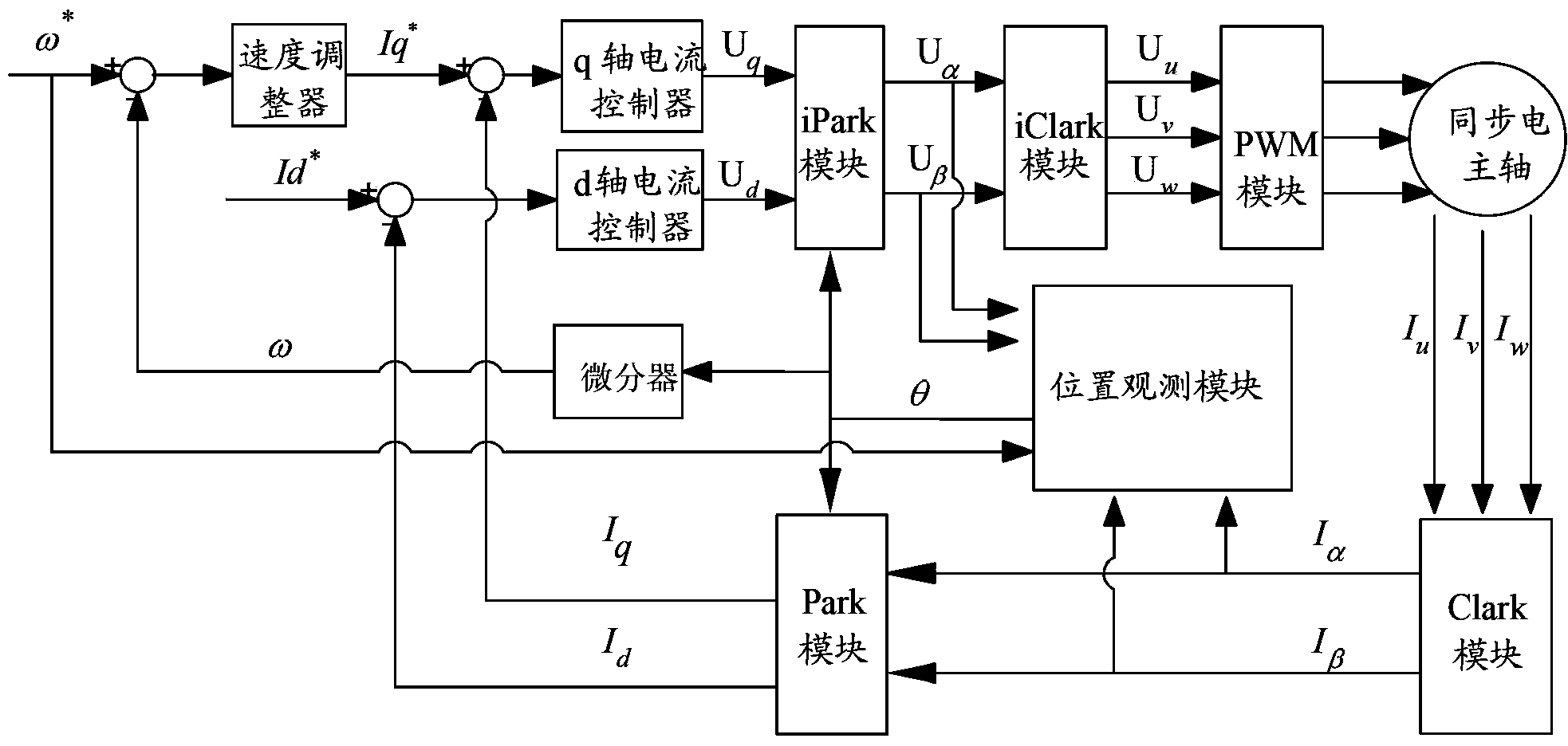
[0031] Such as figure 1 Shown is a structural block diagram of a permanent magnet synchronous electric spindle drive control system in the first embodiment. The permanent magnet synchronous electric spindle drive control system includes a speed regulator, a q-axis current controller, a d-axis current controller, an iPark module, an iClark module, a PWM module, a synchronous electric spindle, a Clark module, a Park module, a position observation module, differentiator. Among them, the speed regulator, q-axis current controller, iPark module, iClark module, PWM (Pulse Width Modulation, pulse width ...


PUM


Abstract

The invention relates to a control system and method for permanent magnet synchronous electric spindle driving. The system carries out vector control to a sensor-less permanent magnet synchronous motor through the adoption of a position observation module. The position observation module comprises a motor model module, a counter electromotive force estimation module and an angle back calculation device, wherein the counter electromotive force estimation module is realized based on an internal model control principle comprising an electric angular velocity summit. The control system and method for the permanent magnet synchronous electric spindle driving can accurately observe the real angle of a rotor, so that the operation performance of the permanent magnet synchronous electric spindle can be improved.

Description

technical field [0001] The invention relates to the field of industrial control, in particular to a permanent magnet synchronous electric spindle drive control system and method. Background technique [0002] The electric spindle is the core component of the machine tool industry. With the continuous development of the equipment manufacturing industry, automated machine tools have higher and higher requirements for the rigidity, angular speed and accuracy of the electric spindle. Traditional machine tools use asynchronous motorized spindles. The slip rate caused by the excitation principle of asynchronous motorized spindles will increase with the increase of the torque load of the motorized spindle, which will reduce the processing stiffness and processing efficiency. For example, the traditional Induction-type electric spindle (belonging to asynchronous electric spindle), in the low-to-medium speed range (10,000 rpm to 30,000 rpm), when the feed angular speed of the machine...

Claims


Application Information

Patent Timeline
IPC IPC(8): H02P6/18H02P6/06H02P21/13H02P27/08
Inventor 吴宏王文杰徐项
Owner GOOGOL TECH SHENZHEN LTD GUANGDONG
Why Eureka
Try Eureka