Apparatus and method for polishing an edge of an article using magnetorheological (MR) fluid

A magnetorheological fluid and magnetorheological technology, applied in the field of edge devices, can solve the problems of not being able to provide material removal rate and not suitable for removing subsurface microcracks, and achieve the effect of increasing material removal rate and reducing polishing time

Inactive Publication Date: 2013-11-20
AGENCY FOR SCI TECH & RES
View PDF5 Cites 7 Cited by
  • Summary
  • Abstract
  • Description
  • Claims
  • Application Information

AI Technical Summary

Problems solved by technology

However, for some applications, such as removal of subsurface damage, including removal of subsurface microcracks, existing MRF technologies do not provide sufficiently favorable material removal rates for the required throughput
Commercially available glass polishing discs are also not suitable for removing subsurface microcracks

Method used


Image

  • Apparatus and method for polishing an edge of an article using magnetorheological (MR) fluid
  • Apparatus and method for polishing an edge of an article using magnetorheological (MR) fluid
  • Apparatus and method for polishing an edge of an article using magnetorheological (MR) fluid

Examples


Embodiment Construction

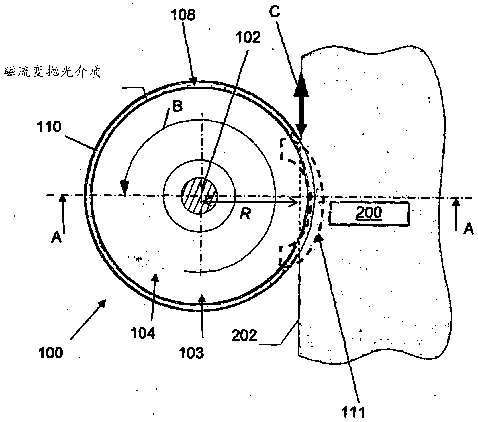
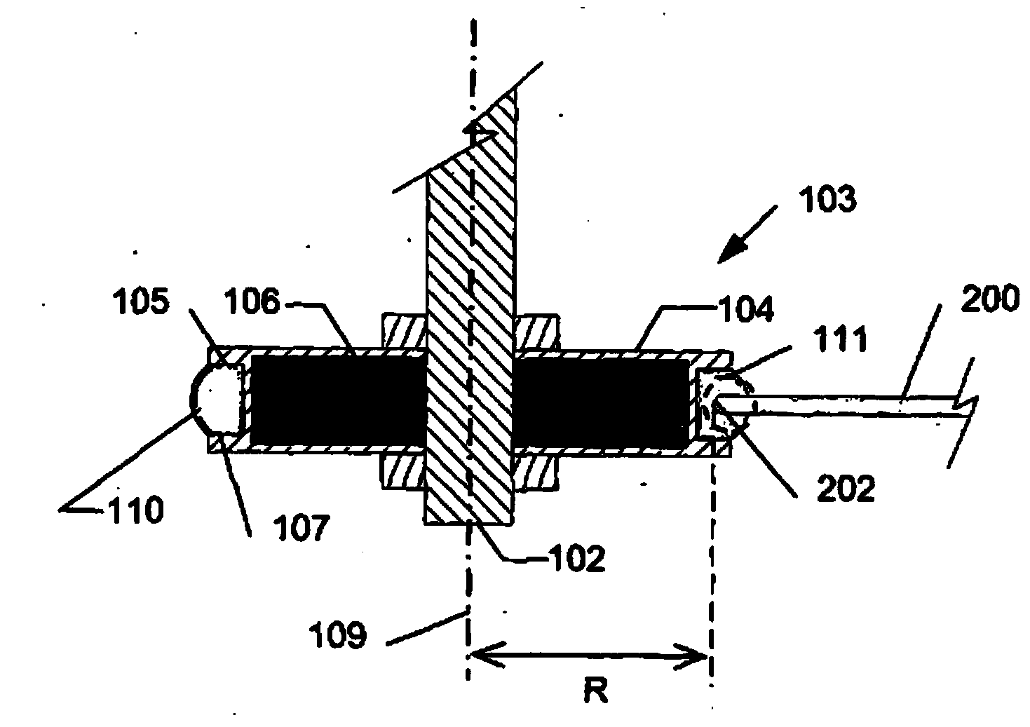
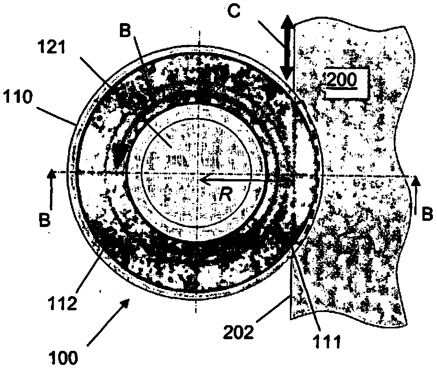
[0037] In order to understand the advantages of embodiments of the present invention, it is advantageous to first explain the various parameters that may affect the material removal rate of a magneto-rheological polishing (MRF) process.

[0038] It has been found that, tribologically, the MRF process is a combination of two and three body abrasive wear. Therefore, the process equations discussed below apply to the MRF process:

[0039] R a = ( R i - R ∞ ) · e - k T p a v H t + R ∞ -...


PUM


Abstract

Disclosed is a method and apparatus for polishing an edge of an article involving providing at least one carrier including: first and second opposing surfaces defining a groove, the first and second opposing surfaces being spaced apart in a first direction to receive the edge; and magnetic field generator configured to provide a magnetic field in the groove to stiffen magnetorheological (MR) fluid disposed in the groove to provide at least one polishing zone; receiving the edge in the polishing zone; and driving relative motion between the at least one carrier and the edge in a second direction substantially transverse to the first direction.

Description

technical field [0001] The present invention relates to an apparatus and method for polishing the edges of objects using magnetorheological fluids, and more particularly, but not exclusively, to apparatus and methods for polishing the edges of large glass sheets. Background technique [0002] It is well known to polish or remove material from the surface of an optical lens by magnetorheological polishing (MRF) using a magnetorheological (MR) fluid. Magnetorheological fluids consist of a suspension of ferro-magnetic particles carried by a carrier fluid. Under the influence of a magnetic field, the ferro-magnetic particles are magnetized by the field and the viscosity of the MR fluid changes, transitioning almost instantaneously from liquid to semi-solid, yet flexible enough to conform to the surface of the workpiece being polished. However, for certain applications, such as removal of subsurface damage, including removal of subsurface microcracks, existing MRF techniques do ...

Claims


Application Information

Patent Timeline
Patent Type & Authority Applications(China)
IPC IPC(8): B24B35/00B24B1/00
CPCB24B1/00B24B35/00B24B1/005B24B9/102
Inventor 万育明·斯蒂芬佐藤隆史
Owner AGENCY FOR SCI TECH & RES
Why Eureka
Try Eureka