Gearbox unit

A technology of transmissions and components, applied in vehicle gearboxes, transmission components, components with teeth, etc., can solve problems such as low-efficiency operation of internal combustion engines and/or electric motors, and achieve high-efficiency operation

Inactive Publication Date: 2013-11-20
MAGNA POWERTRAIN AG & CO KG
View PDF9 Cites 10 Cited by
  • Summary
  • Abstract
  • Description
  • Claims
  • Application Information

AI Technical Summary

Problems solved by technology

[0004] However, since the entire driving range of the vehicle is covered by the same transmission configuration, inefficient operation of the internal combustion engine and / or electric machine (multiple electric machines) may occur under certain driving conditions

Method used


Image

  • Gearbox unit

Examples


Embodiment Construction

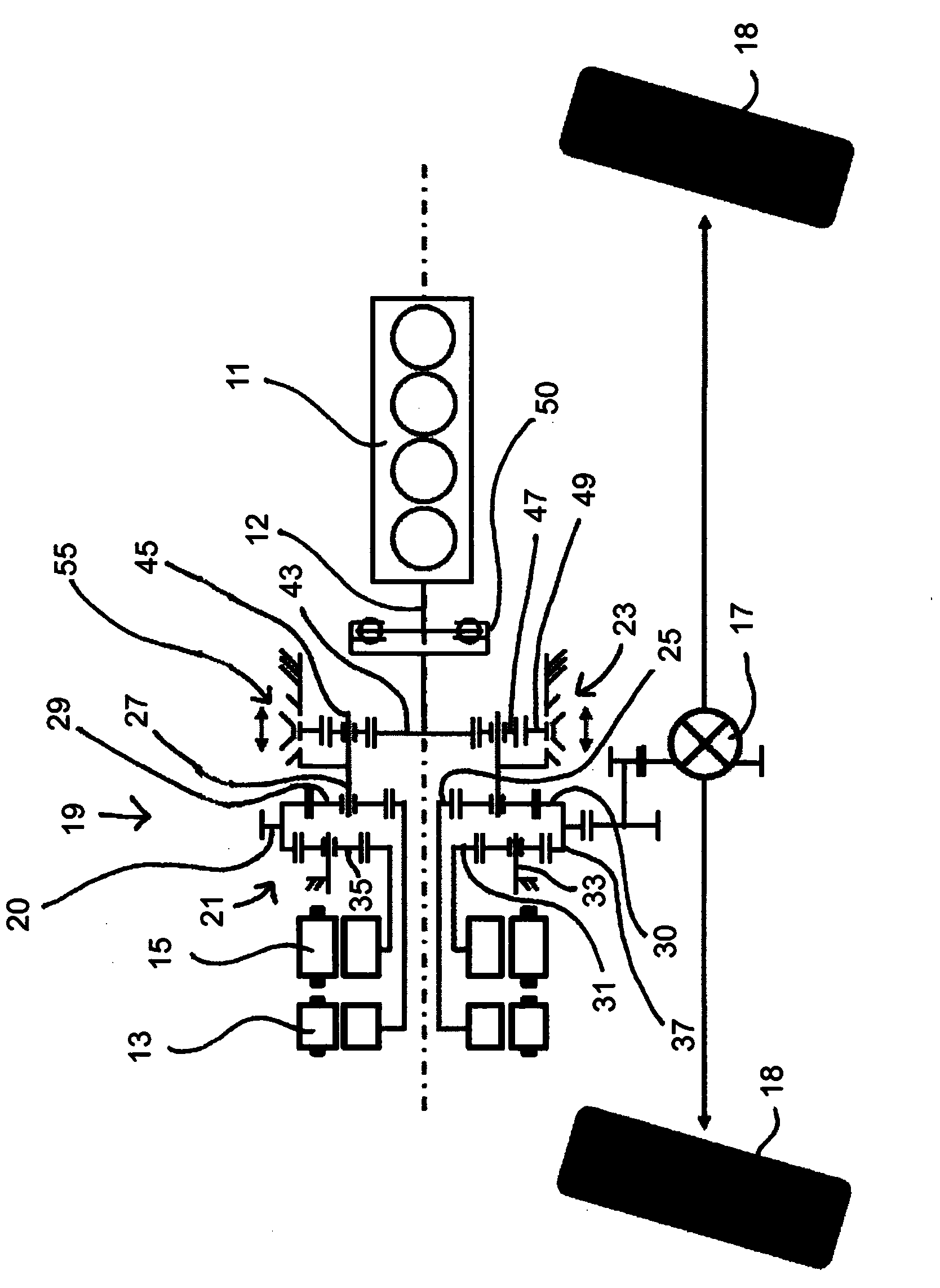
[0020] The drive train of the vehicle includes an internal combustion engine 11 , a first electric machine 13 , a second electric machine 15 and an axle differential 17 . The first electric machine 13 and the second electric machine 15 are arranged coaxially to each other and to the output shaft 12 of the internal combustion engine 11 and can be operated optionally as a motor or as a generator. as from figure 1 As can be seen in , the second motor 15 is larger than the first motor 13 . The internal combustion engine 11 , the first electric machine 13 and the second electric machine 15 are interconnected via a transmission unit 19 . The driven wheel 20 of the transmission unit 19 is drivingly coupled to the axle differential 17, for example via spur gear teeth (or another type of traction drive or belt drive), so that the internal combustion engine 11 and / or the two electric machines 13, 15 can thus be connected The drive power is delivered to the wheels 18 of the vehicle. T...


PUM


Abstract

The invention relates to a gearbox unit for a drive train of a motor vehicle, the drive train comprising at least one internal combustion engine and a first electric motor (and preferably also a second electric motor), comprising a first planetary gear system, a second, switchable planetary gear system, and a clutch for switching the second planetary gear system between a first operating state and a second operating state. The first planetary gear system comprises at least one first member for coupling to the first electric motor, a second member for taking up a drive power from the internal combustion motor, and a third member for outputting drive power. The second planetary gear system comprises at least one first member for coupling to the internal combustion engine, a second member for coupling to the second member of the first planetary gear system, and a third member. In the first operating state, the coupling holds the third member of the second planetary gear system. In the second operating state, the coupling couples the third member of the second planetary gear system in a rotationally fixed manner to the first or second member of the second planetary gear system.

Description

technical field [0001] The invention relates to a transmission unit for a vehicle drive train having at least one internal combustion engine and a first electric machine (and preferably also a second electric machine). Background technique [0002] Hybrid powertrains for vehicles using an internal combustion engine and one or more electric machines as drive sources are characterized by relatively high efficiency and the possibility of saving fuel. In addition, compared to drive systems with an internal combustion engine as the sole drive source, additional functions are offered, such as noiseless and emission-free electric driving, electric braking with braking energy recovery (regeneration) or a combination of motors Acceleration rises (electric assist). By using an additional, ie second, electric machine, a better match to the instantaneous power demand and improved regeneration can be achieved, especially when the two electric machines are of different sizes, ie designed...

Claims


Application Information

Patent Timeline
Patent Type & Authority Applications(China)
IPC IPC(8): B60K6/445B60K6/547B60K6/365F16H3/72F16H37/08F16H3/54B60K6/26
CPCY02T10/6239F16H2200/2097F16H3/728F16H2200/2064F16H2200/2035F16H3/54B60K2006/266F16H2200/201B60K6/365B60K6/547F16H2037/0873B60K6/445Y02T10/62
Inventor M.比奇勒R.朔伊彻
Owner MAGNA POWERTRAIN AG & CO KG
Why Eureka
Try Eureka