

A system and method for catalyst particle recovery
A technology of catalyst particles and recovery devices, which is applied in the direction of separating sediments by centrifugal force, can solve problems such as restricting process development, achieve the effects of ensuring accuracy, improving efficiency, and solving adverse effects
- Summary
- Abstract
- Description
- Claims
- Application Information
AI Technical Summary
Problems solved by technology
Method used
Image

Examples
Embodiment 1
[0038] Example 1: Recovery System
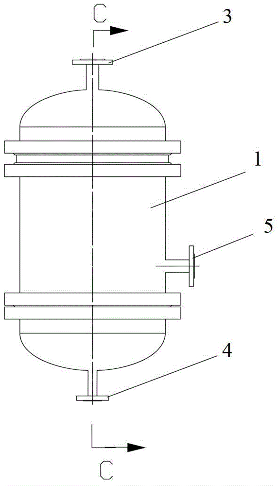
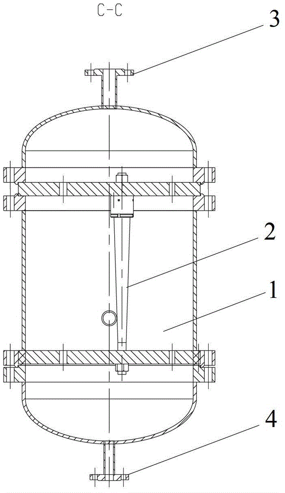
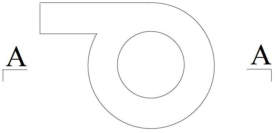
[0039] see figure 1 , figure 2, Figure 3a , Figure 3b , Figure 5 , The catalyst particle recovery system includes a cylindrical recovery device 1, 38 swirl tubes 2 are vertically arranged in the recovery device 1, and the shell diameter of the recovery device 1 is 800mm and the height is 1500mm. The top of the recovery device is provided with a clear liquid outlet 3, the bottom is provided with a catalyst recovery liquid outlet 4, and the side wall is provided with a filtrate inlet 5.
[0040] 38 swirl tubes 2 are vertically arranged in the recovery device, distributed in an even array, and the side wall is provided with a filtrate inlet 5, which is 350mm away from the bottom of the recovery device 1. After the filtrate enters, the liquid level rises to the position of the swirl tube inlet 6, And enter the swirl tube 2. The diameter of the swirl tube distribution area is 740 mm. The feed inlet 6 of the swirl tube 2 is a tangential...
Embodiment 2
[0043] Example 2: Recovery system
[0044] The system for recovering catalyst particles includes a cylindrical recovery device in which 18 swirl tubes are vertically arranged. The shell diameter of the recovery device 1 is 500mm and the height is 1200mm. The top of the recovery device is provided with a clear liquid outlet, the bottom is provided with a catalyst recovery liquid outlet, and the side wall is provided with a filtrate inlet.
[0045] There are 18 swirl tubes installed vertically in the recovery device, which are evenly distributed in an array. There is a filtrate inlet on the side wall. The filtrate inlet is 300mm away from the bottom of the recovery device. . The diameter of the swirl tube distribution area is 450mm. The feed inlet of the swirl tube is a tangential inlet, and the feed inlets are all arranged on the same horizontal plane. The recovery device is made of 316L stainless steel, and the inner surface is sprayed with 4 layers of epoxy resin (Xi'an Ti...
Embodiment 3
[0048] Example 3: Recovery of Catalyst Particles
[0049] Sinopec Catalyst Qilu Branch Catalytic Cracking Catalyst Production Workshop (Catalyst No. 2 Workshop), the catalyst particles are transported out of the reactor with washing water, filtered through a bag filter, and the filtrate flow rate is 30m 3 / h. see Figure 5 , The recovery system is provided with two recovery devices 1, and the structure of the recovery device 1 is as in embodiment 1. Each processing capacity is 15m 3 / h. Five batches of filtrate were processed and analyzed for particle size, in which the catalyst particle distribution is shown in Table 1. In Table 1, "1-in" means the first batch of filtrate, "1-turbidity" means the first batch of filtrate passed through the recovery device, and the turbid liquid from the catalyst recovery liquid outlet, and so on.
[0050] Table 1: Particle distribution of recovery unit inlet and turbid liquid outlet
[0051]
[0052] The filtrate passes through the li...
PUM
| Property | Measurement | Unit |
|---|---|---|
| particle diameter | aaaaa | aaaaa |
| diameter | aaaaa | aaaaa |
| height | aaaaa | aaaaa |
Abstract
Description
Claims
Application Information