Combined type roller mold and water stopping copper strip forming machine

A combined, rolling die technology, applied in the field of sheet metal rolling, can solve the problems of low overall disassembly and assembly work efficiency and high man-hour cost, and achieve the effects of improving work efficiency, saving die cost and improving work efficiency.

Active Publication Date: 2013-11-27
SINOHYDRO BUREAU 12 CO LTD
View PDF7 Cites 1 Cited by
  • Summary
  • Abstract
  • Description
  • Claims
  • Application Information

AI Technical Summary

Problems solved by technology

The overall disassembly and assembly operation efficiency of the traditional one-piece rolling die is low, the cost of man-hours is high, and the employees are irritated. It is urgent to invent a rolling die that does not require overall disassembly, which is applied to the water-stop copper strip forming machine to improve the replacement of dies. s efficiency

Method used


Image

  • Combined type roller mold and water stopping copper strip forming machine
  • Combined type roller mold and water stopping copper strip forming machine
  • Combined type roller mold and water stopping copper strip forming machine

Examples


Embodiment 1

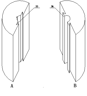
[0031] Embodiment 1——combined roller mold group, see Picture 1-1 , Figure 1-2 , Figure 1-3 .

[0032] A pair of combined roller mold sets, the rolling modules of the rolling mold on the upper roller shaft 17 are side pressing piece 29 + upper rolling wheel 30 + middle sleeve 31 + upper rolling wheel 30 + side pressing piece 29, and the rolling modules on the lower roller shaft 18 are in turn It is the inverted side pressing sheet 32+lower roller 33+flange sheet 34+lower roller 33+inverted side pressing sheet 32. After the size processing of each pair of rolling die structural components is completed, each rolling module is cut in half along the axial direction into a part A with a dovetail groove (in this example, the middle point of the key groove bottom and the axis center of the roller The connection line is perpendicular to the mating surface of this part), the other half of the B part with the dovetail boss, the two roller mold parts can be separated and combined alo...

Embodiment 2

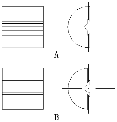
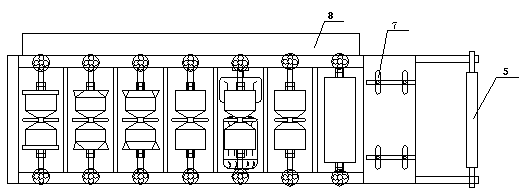
[0034] Embodiment 2——waterproof copper strip forming machine, see Figure 2-1 , 2-2 , 3-3 and Figure 3-1 , 3-2 , 3-3, 3-4, 3-5, 3-6, 3-7.

[0035] A water-stop copper belt molding machine using a combined roller mold set, including a frame 1, a power component composed of a drive motor 2, a reducer 3, and a transmission chain system 4 on the frame, a roller bracket 5, and a feeding platform 7 The feed part that is formed, the forming part that the bearing 28 that 7 pairs of combined roller mold groups, gap adjusting device 6, fixed roller axle are formed. The lower roller of each pair of roller mold sets is a driving wheel; the upper roller of each pair of roller mold sets is a passive wheel, and its shaft is connected to the frame through a gap adjustment device 6, which can adjust the gap between the working busbars of the pair of roller molds . The power comes from the driving motor 2, which is connected to each lower roller by the transmission chain system 4. Becaus...


PUM


Abstract

The invention belongs to the field of sheet metal rolling, and aims to solve the technical problems that an axial replacement structure of a roller type mold is designed, so that a shaft is not required to be detached when the roller type mold is replaced, and the replacement is simple and convenient. The combined type roller mold comprises a roller shaft (27) provided with a shaft key (24), wherein the shaft is sleeved with a rolling mold provided with a key groove and matched with the shaft; the rolling mold is provided with a plurality of rolling modules which are axially pressed into a whole; and a roller pressing sleeve (25) and a gland nut (26) are arranged at two ends of the rolling mold. The combined type roller mold is characterized in that each rolling module is formed by a part A and a part B which are radially spliced, one or two dovetail grooves (35) is or are formed in a matching surface of the rolling module part A, and one or two dovetail bosses (36) is or are arranged in a corresponding position or positions on a matching surface of the rolling module part B in a matching manner; and the key groove is formed in the part A or the part B. A water stopping copper strip forming machine uses seven pairs of the combined type roller mold groups.

Description

technical field [0001] The invention belongs to the field of sheet metal rolling, in particular to a combined roller mold and a water-stop copper strip forming machine using the mold. [0002] Background technique [0003] Rolling and rolling processes are commonly used in the processing of thin metal sheets. Common rolls or rolling dies are mostly one-piece. When it is necessary to adjust the working busbar, the roller shaft must be removed as a whole, the one-piece roll or rolling die must be removed, and a new one-piece roll or rolling die must be replaced. roller. This method is labor-intensive, time-consuming and inefficient. Chinese patent CN2428237 discloses a combined roll for cold-bending profile forming. The one-piece roll is decomposed into multiple parts that can be combined axially in the radial direction. When updating the roll, only the part that needs to be updated needs to be replaced without the overall update. Improve operating efficiency to a certain ...

Claims


Application Information

Patent Timeline
Patent Type & Authority Applications(China)
IPC IPC(8): B21D13/04B21D37/00
Inventor 姜国平
Owner SINOHYDRO BUREAU 12 CO LTD
Why Eureka
Try Eureka