Pumping hydraulic system

A hydraulic system and pumping technology, applied in the direction of fluid pressure actuators, servo motors, servo motor components, etc., can solve the problems of increasing the vertical vibration amplitude of the boom, the difficulty, and the discontinuity of the concrete delivery process, to achieve Effects of reduced commutation response time, improved operability, and reduced vibration amplitude

Active Publication Date: 2013-11-27
河北雷萨重型工程机械有限责任公司
View PDF7 Cites 19 Cited by
  • Summary
  • Abstract
  • Description
  • Claims
  • Application Information

AI Technical Summary

Problems solved by technology

The existence of the reversing response time t, especially if the reversing response time t is too long, will lead to the discontinuity of the concrete conveying process and affect the concrete conveying efficiency. The amplitude of up and down vibration in
but corresponds to

Method used


Image

  • Pumping hydraulic system
  • Pumping hydraulic system
  • Pumping hydraulic system

Examples


Example Embodiment

[0052] The specific embodiments of the present invention will be described in detail below with reference to the accompanying drawings. It should be understood that the specific embodiments described herein are only used to illustrate and explain the present invention, and not to limit the present invention.

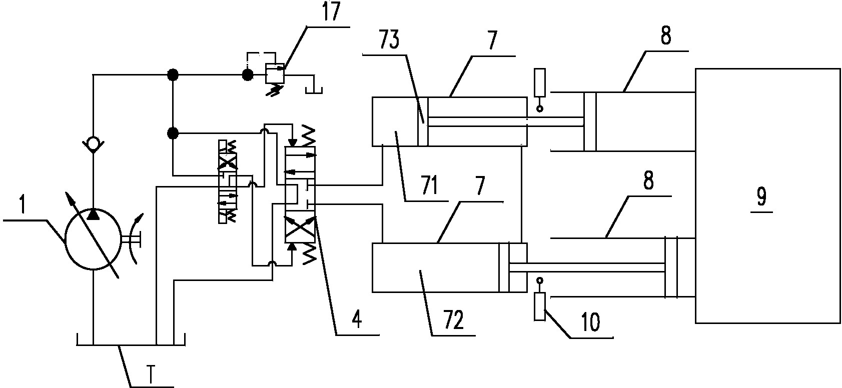
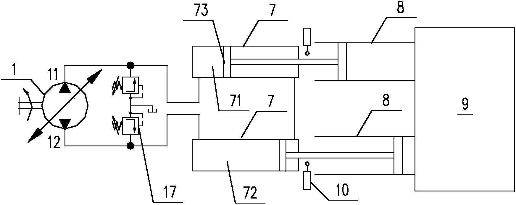
[0053] Such as Figure 4 to Figure 7 As shown, the present invention provides a pumping hydraulic system. The system includes a hydraulic oil pump 1 and a working oil cylinder 7. The hydraulic oil pump 1 pumps hydraulic oil to the working oil cylinder 7 to push the piston rod of the working oil cylinder 7 through a hydraulic cylinder expansion control oil path 73 reciprocating movement. The pumping hydraulic system also includes an accumulator 5 and a control valve 6. The accumulator 5 is hydraulically connected to the working cylinder 7 via the control valve 6. The control valve 6 is used to control the energy storage during the reciprocating movement of the piston rod 73...


PUM


Abstract

The invention discloses a pumping hydraulic system which comprises a hydraulic oil pump (1), an energy accumulator (5), a control valve (6) and operating cylinders (7), wherein the hydraulic oil pump is used for pumping hydraulic oil to the operating cylinders through a hydraulic cylinder telescopic control oil line, so as to push piston rods (73) of the operating cylinders to perform reciprocating motion; the energy accumulator is in hydraulic connection to the operating cylinders through the control valve; the control valve is used for controlling the energy accumulator to convey hydraulic oil to piston rod actuating chambers of the operating cylinders during the process of direction change of the piston rods when the piston rods perform reciprocating motion; so as to push the piston rods to change directions. According to the pumping hydraulic system provided by the invention, the energy accumulator and the control valve are adopted, so that the hydraulic oil can be conveyed to the piston rod actuating chambers timely with the help of release of pressure oil in the energy accumulator to push the piston rods to change direction rapidly and reduce response time t of direction change of the piston rods as far as possible, the continuity of concrete pumping is realized, the pumping efficiency is improved, meanwhile, the vibration amplitude of a placing boom is reduced, and the operating performance of concrete construction is improved.

Description

technical field [0001] The invention belongs to the technical field of concrete machinery, and in particular relates to a pumping hydraulic system capable of realizing quick start of oil cylinder reversing. Background technique [0002] Such as figure 1 and figure 2 Shown are hydraulic schematic diagrams of an open and closed pumping hydraulic system according to the prior art, respectively. Its working principle is: the hydraulic oil pump 1 provides hydraulic power for the system, the overflow valve 17 limits the maximum working pressure of the hydraulic system, and the hydraulic oil pump 1 pumps hydraulic oil to the working cylinder 7 through the common hydraulic cylinder telescopic control oil circuit to push the working cylinder 7 The piston rod 73 moves back and forth, and the piston rod 73 is connected to the concrete cylinder 8 and the hopper 9. The working cylinder 7 generally includes two connected cylinders. exist figure 2 and image 3 Among them, the teles...

Claims


Application Information

Patent Timeline
IPC IPC(8): F15B11/17F15B1/02F15B13/02E04G21/02
Inventor 张华刘明清张鑫刘震捷
Owner 河北雷萨重型工程机械有限责任公司
Why Eureka
Try Eureka