Noise power generator

A technology of noise power generation and power generation devices, applied in electromechanical devices, electrical components, etc., can solve the problems of narrow noise absorption frequency, low sound-to-electric conversion efficiency, and non-concentrated sound energy, achieving high power density, high energy conversion efficiency, Efficient use of noise effects

Active Publication Date: 2013-11-27
平邑经济开发区投资发展有限公司
5 Cites 2 Cited by

AI-Extracted Technical Summary

Problems solved by technology

[0005] Aiming at the problems of narrow noise absorption frequency, low sound-to-electricity conversion efficiency, and non-concentrated sound energy in the existing traditional noise power generation device, the...

Method used

Visible by Fig. 3, form a structural unit jointly by four Helmholtz chambers and rear chamber and internal structure thereof, 4 structural units correspond to four sides of cuboid, and Helmholtz chamber passes catheter 2 and external world Connected, the inner cavity 7 run...

Abstract

The invention discloses a noise power generator which comprises Helmholtz cavities, guide pipes, generating devices, elastic walls, rear chambers, circuit boards and inner cavities. The noise power generator is a cuboid with the inner cavities, the Helmholtz cavities are arranged in the four side faces of the noise power generator respectively, the inner cavities penetrate through the top face and the bottom face of the cuboid, the outer sides of the Helmholtz cavities are communicated with the outside through the guide pipes, the elastic walls are arranged on the inner sides of the Helmholtz cavities, the rear chambers are arranged on the inner sides of the elastic walls, the generating devices are arranged in the rear chambers, the inner cavities are arranged on the inner sides of the rear chambers, the circuit boards are arranged in the inner cavities and are in load connection with the generating devices and the outside respectively, and therefore noise power generation control is achieved. According to the noise power generator, the Helmholtz cavities and paraphrase holes are effectively utilized to efficiently absorb noise, and the aim of utilizing sound energy in a centralized mode is achieved.

Application Domain

Technology Topic

Image

  • Noise power generator
  • Noise power generator
  • Noise power generator

Examples

  • Experimental program(1)

Example Embodiment

[0020] The present invention will be further described below in conjunction with the accompanying drawings.
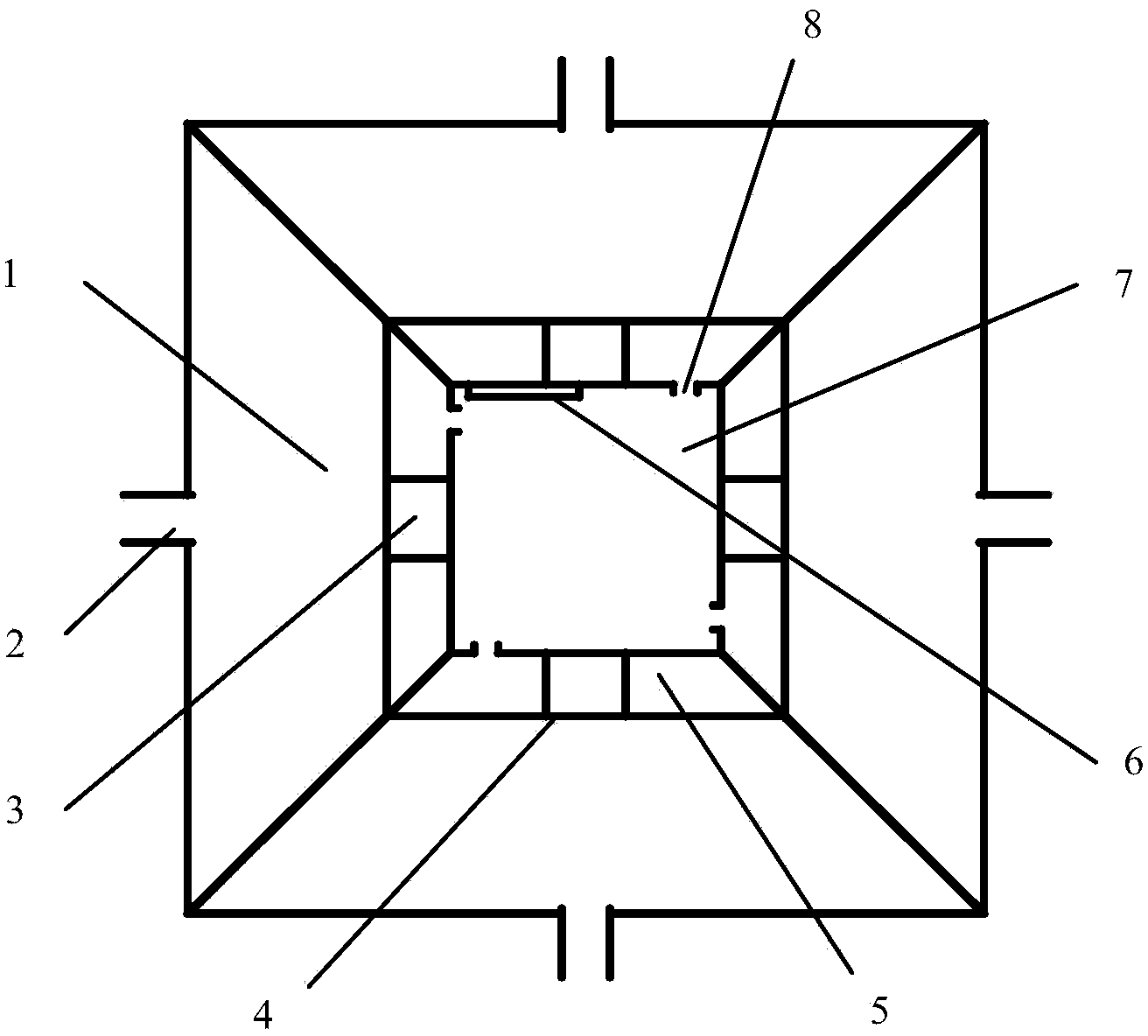
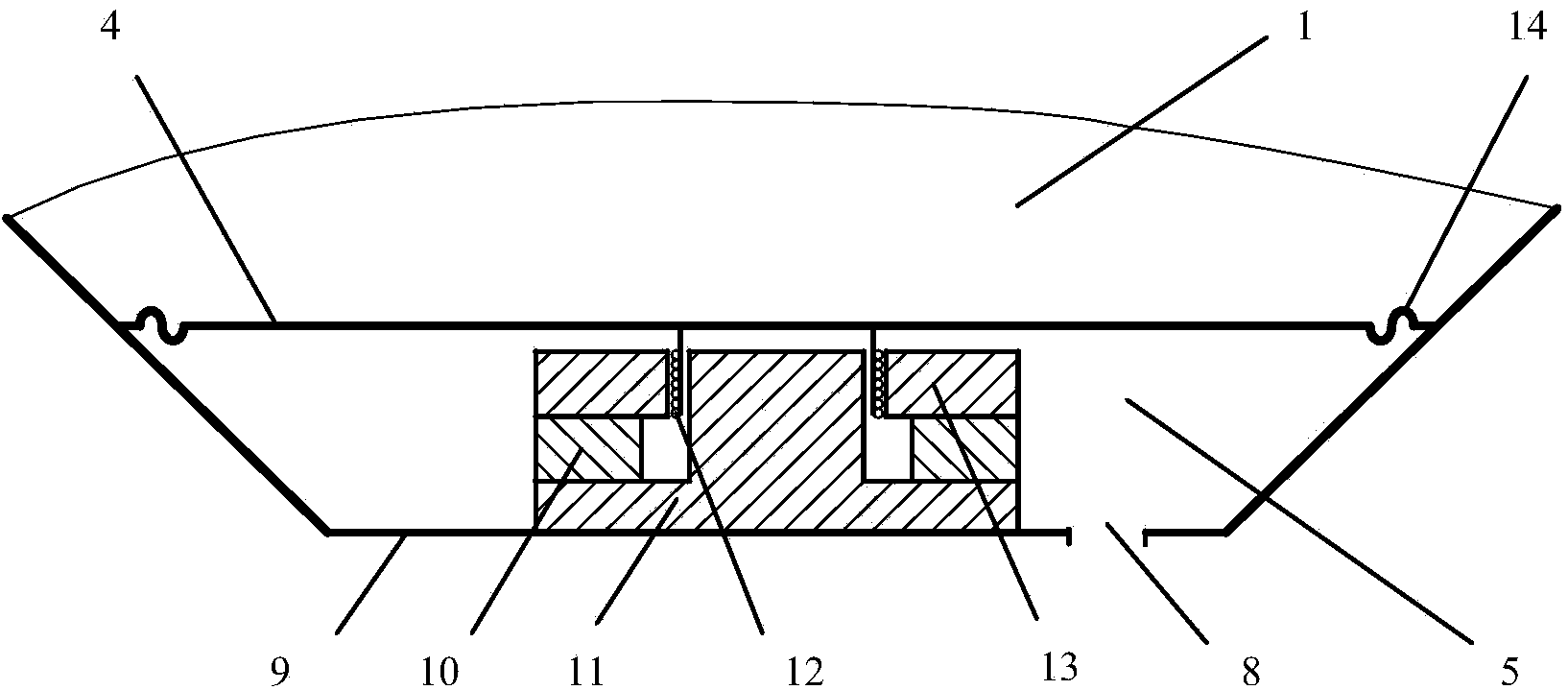
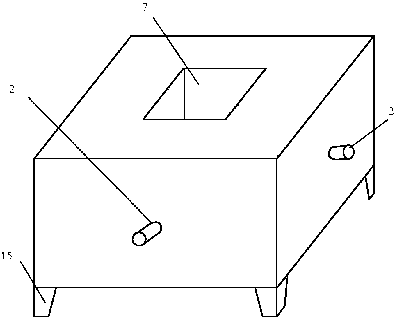
[0021] Depend on figure 1 and 2 It can be seen that the noise generating device of the present invention has four similar structural units, and each structural unit includes a Helmholtz cavity 1, a conduit 2, a power generating device 3, an elastic wall 4, a rear chamber 5, a circuit board 6, an inner cavity 7, The phase reversal hole 8 and the rear wall 9, the Helmholtz cavity 1 communicates with the outside world through the conduit 2, the inner side of the Helmholtz cavity 1 is provided with an elastic wall 4, and the two ends of the elastic wall 4 are provided with folds. The ring 14 is connected with the rigid side wall of the Helmholtz cavity 1. The rear chamber 5 is located at the rear of the Helmholtz cavity 1 and is isolated from each other by the elastic wall 4. A phase inversion hole 8 is opened, and the rear chamber 5 is communicated with the inner cavity 7 through the phase inversion hole 8 .
[0022] Depend on figure 2 It can be seen that the power generating device 3 installed in the rear chamber 5 includes a permanent magnet 10, a T iron 11, a coil 12 and a magnetic conducting plate 13. The T iron 11 is installed on the rear wall 9 of the rear chamber 5, and the T iron 11 is connected to the permanent magnet 10. One side end face of the permanent magnet 10 is connected to the other end face of the permanent magnet 10 is connected to the magnetic conducting plate 13. There is an air gap of a certain length at the intersection of the magnetic conducting plate 13 and the T iron 11. Magnetic field, the skeleton of the coil 12 is fixed on the elastic wall 4 , and the main part of the coil 12 is located in the air gap between the magnetic conducting plate 13 and the T iron 11 . A circuit board 6 is arranged in the inner cavity 7, and is respectively connected with the power generating device 3 and the external load, so as to realize the noise power generation control.
[0023] Depend on image 3 It can be seen that a structural unit is composed of four Helmholtz cavities, the back chamber and its internal structure. The four structural units correspond to the four sides of the cuboid. The Helmholtz cavities communicate with the outside world through the conduit 2, and the inner cavity 7 runs through The top and bottom surfaces of the cuboid and the bottom of the cuboid are provided with feet 15 , through which the noise generating device of the present invention can be easily fixed, and it is also convenient for movement and temporary erection.
[0024] It should be pointed out that for those skilled in the art, without departing from the principle of the present invention, several improvements and modifications can also be made, and these improvements and modifications should also be regarded as the protection scope of the present invention. All components not specified in this embodiment can be implemented by existing technologies.

PUM

no PUM

Description & Claims & Application Information

We can also present the details of the Description, Claims and Application information to help users get a comprehensive understanding of the technical details of the patent, such as background art, summary of invention, brief description of drawings, description of embodiments, and other original content. On the other hand, users can also determine the specific scope of protection of the technology through the list of claims; as well as understand the changes in the life cycle of the technology with the presentation of the patent timeline. Login to view more.

Similar technology patents

Brushless Motor and System Thereof

InactiveUS20170047834A1Risk be eliminate and substantially reduceImprove energy conversion efficiencyAssociation with control/drive circuitsSalient polesControl systemBrushless motors
Owner:FOSTER ASSETS CORPORATION

Classification and recommendation of technical efficacy words

Why Eureka
Try Eureka