A filter circuit applied to three-phase converter

A three-phase converter and filter circuit technology, applied in electrical components, output power conversion devices, etc., can solve the problems of high cost, large volume, poor filtering effect, etc., to reduce loss, small size, and good absorption effect. Effect

Active Publication Date: 2015-11-25
LANGFANG IN POWER ELECTRIC +1
View PDF4 Cites 1 Cited by
  • Summary
  • Abstract
  • Description
  • Claims
  • Application Information

AI Technical Summary

Problems solved by technology

[0007] The utility model aims at the problems of poor filtering effect, large volume and high cost of traditional filter circuits, and develops a filter circuit applied to three-phase converters, which has high filtering precision, small size, low cost and high stability. advantage

Method used


Image

  • A filter circuit applied to three-phase converter
  • A filter circuit applied to three-phase converter
  • A filter circuit applied to three-phase converter

Examples


Embodiment Construction

[0026] The technical scheme of the utility model will be further described below in conjunction with the accompanying drawings and specific embodiments.

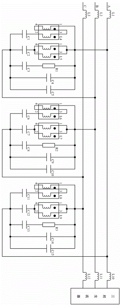
[0027] Such as figure 1 As shown, the utility model is a filter circuit applied to a three-phase converter, and the circuit includes:

[0028] The first incoming line inductance L1, the second incoming line inductance L2, the third incoming line inductance L3;

[0029] The fourth filter inductor L4, the fifth filter inductor L5, the sixth filter inductor L6, the seventh filter inductor L7, the eighth filter inductor L8, and the ninth filter inductor L9;

[0030] First filter capacitor C1, second filter capacitor C2, third filter capacitor C3, fourth capacitor C4, fifth capacitor C5, sixth filter capacitor C6, seventh filter capacitor C7, eighth filter capacitor C8, ninth capacitor C9 , the tenth capacitor C10, the eleventh filter capacitor C11, the twelfth filter capacitor C12, the thirteenth filter capacitor C13, the four...


PUM


Abstract

The invention relates to a filter circuit, wherein the performance requirement of the filter circuit for a three-phase converter is that small high frequency harmonic content is output. The circuit comprises wire-incoming inductors (L1, L2 and L3), filter inductors (L4, L5, L6, L7, L8 and L9), filter capacitors (C1, C2, C3, C6, C7, C8, C11, C12 and C13), damping resistors (R1, R2 and R3) and bridge side inductors (L10, L11 and L12). The filter circuit has the advantages that the filter circuit can still filter switching ripples at the position of a switching frequency and switching ripples several times of the switching frequency effectively at lower switching frequency; a single filter branch circuit is arranged, so that for a certain specific time ripple circuit, the absorption effect is better, meanwhile current flowing through the damping resistors can be reduced, loss of the damping resistors is reduced, and system stability is improved; the filter circuit is small in size, cost is reduced, and design space is saved.

Description

technical field [0001] The utility model belongs to the field of electric energy quality control and electric energy-saving equipment manufacturing, and in particular relates to a filter circuit with less output high-frequency harmonic content required for the performance of a three-phase converter. Background technique [0002] With the rapid development of the national economy and the continuous improvement of the level of science and technology, under the environment of carrying out energy conservation and efficiency enhancement, and building a resource-saving and environment-friendly society, my country's economy has gradually entered the "energy saving and emission reduction, high quality and high efficiency, low carbon In the new era of "Industry", power electronic products have been widely used, followed by the deteriorating power supply quality of the power grid, the distortion of the grid voltage waveform, the greatly reduced power factor, and the serious harm of harm...

Claims


Application Information

Patent Timeline
Patent Type & Authority Patents(China)
IPC IPC(8): H02M1/12
Inventor 索红亮娄丽丽
Owner LANGFANG IN POWER ELECTRIC
Why Eureka
Try Eureka