
X-ray imaging robot and mechanical arm thereof

An X-ray and robot technology, applied in the field of medical devices, can solve the problems of inconvenient operation, no driving links for joints, inflexible movement, etc., and achieve the effect of large activity space, high flexibility, and reduced inertia

Active Publication Date: 2013-12-04
SHENZHEN INST OF ADVANCED TECH CHINESE ACAD OF SCI
View PDF5 Cites 16 Cited by
  • Summary
  • Abstract
  • Description
  • Claims
  • Application Information

AI Technical Summary

Problems solved by technology

The traditional C-arm is mainly operated manually or electrically, and the movement is relatively inflexible. Only a few models can provide very limited 3D imaging functions, and the operation is still very inconvenient
For this reason, some researchers improved the traditional C arm, such as Binder N et al. (Binder N., Bodensteiner C., L., et al.. The Surgeon's Third Hand an Interactive Robotic C-Arm Fluoroscope. Mobile Robotics–Moving Intelligence, 2007, 403-418) to improve the controllability of the C-arm by increasing the drive link and kinematic modeling, but Still does not change the limitations of the traditional C-arm in terms of mechanism and degree of freedom configuration
At the same time, some foreign manufacturers have also carried out related research. For example, the miniature C-arm launched by OrthoScan HD with Flat Detector (http: / / orthoscan.com / mini-c-arms / fd / fd-summary) in the United States adopts the robot arm bracket To improve the flexibility of the C-arm, but most of the joints do not have driving links, and are mainly aimed at X-ray imaging of limbs and other parts, requiring manual operation, making it difficult to achieve 3D imaging
In addition, the Chinese patent application with the application number CN200910002386.9 proposes a C-arm placed on the robot arm and applied to Siemens Artis Zeego. Although it can improve the flexibility of large angiography machines, the tandem mechanism used The arm is bulky and can only be installed in very large operating rooms

Method used


Image

  • X-ray imaging robot and mechanical arm thereof
  • X-ray imaging robot and mechanical arm thereof
  • X-ray imaging robot and mechanical arm thereof

Examples


Embodiment Construction

[0032] The present invention will be described in further detail below in conjunction with the accompanying drawings and specific embodiments.

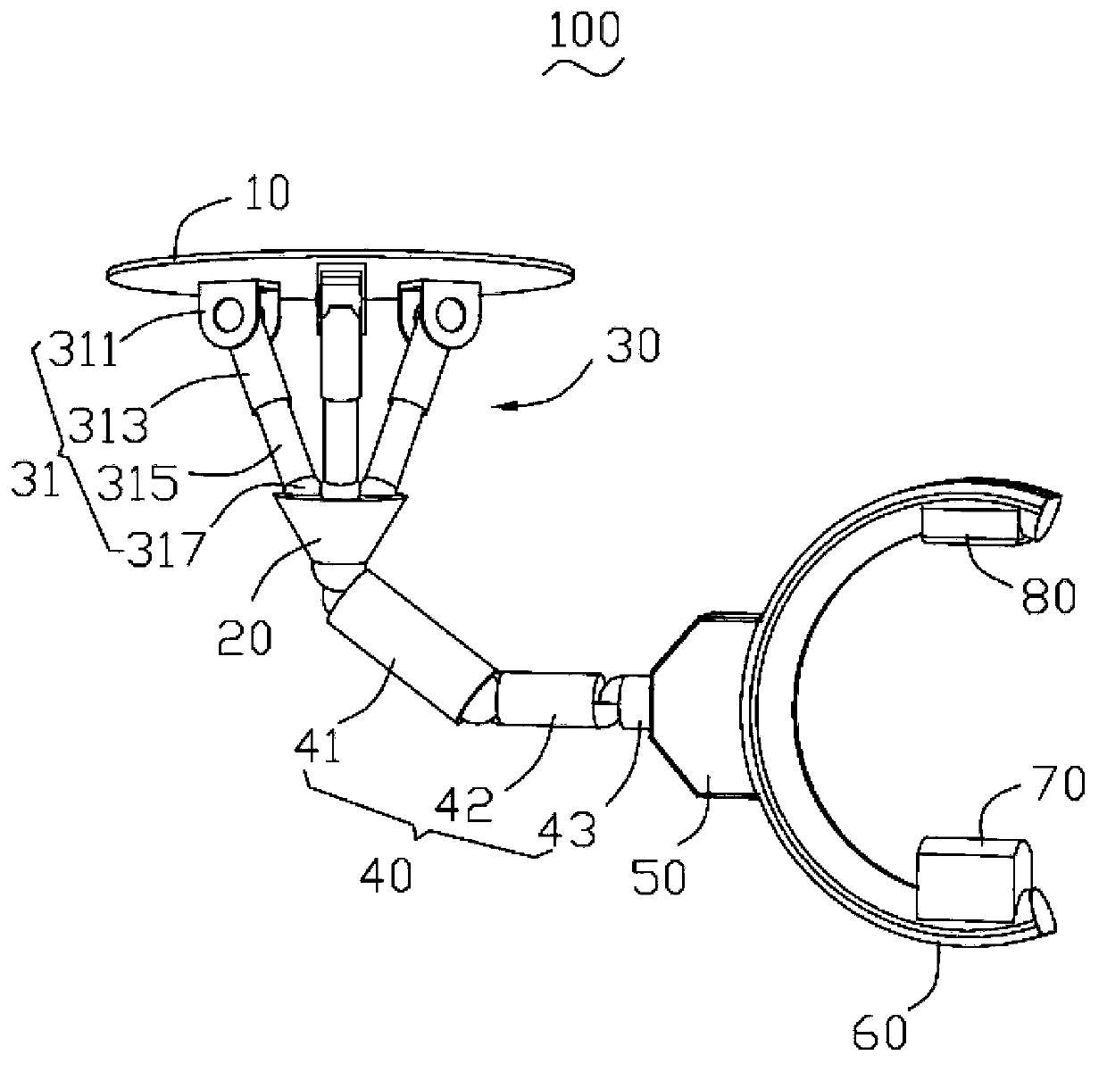
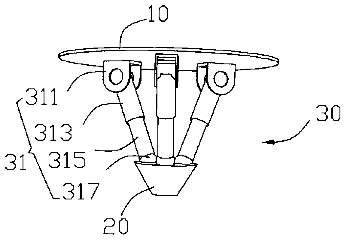
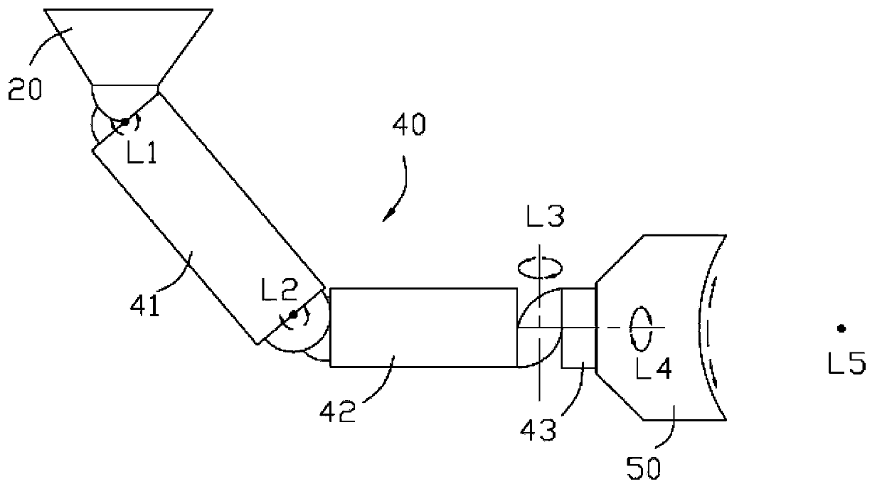
[0033] see figure 1 , a preferred embodiment of the present invention provides an X-ray imaging robot 100, which has multiple degrees of freedom and is used for three-dimensional imaging during surgery. The X-ray imaging robot includes a fixed platform 10, a moving platform 20, a A parallel mechanism 30 , a series mechanism 40 , a bracket 50 , a C-shaped track 60 , an X-ray source 70 and an image detector 80 .

[0034] The fixed platform 10 is used to fix the X-ray imaging robot 100. It can be understood that, according to the specific use of the X-ray imaging robot 100, the fixed platform 10 can be fixed on the ceiling, the ground, the wall or other machines. on the stand of the table or device. In this embodiment, the fixed platform 10 is a flat plate structure.

[0035] The moving platform 20 has one translational degree of free...


PUM


Abstract

The invention provides an X-ray imaging robot which comprises a fixed platform used for fixing an X-ray imaging robot body, a movable platform, a parallel mechanism, a serial mechanism, a supporting frame, a C-shaped rail, an X-ray source and an image detector. The movable platform has one translational moving freedom degree and two rotational freedom degrees, the parallel mechanism is arranged between the fixed platform and the movable platform and is composed of a plurality of branched chains in a parallel connection mode, the serial mechanism comprises a plurality of supporting arms, the movable platform and the supporting arms are in series connection through revolute pairs in sequence, the supporting frame is connected to the end, far away from the movable platform, in the serial mechanism through a revolute pair, the C-shaped rail and the supporting frame are connected though a sliding pair in circular arc tracks, and the X-ray source and the image detector are arranged on the inner wall of the C-shaped rail and are arranged oppositely. The X-ray imaging robot can effectively carries out imaging in different directions in a three-dimensional space, and has the advantages of being large in moving space, and high in precision and rigidity. The invention further provides a mechanical arm of the X-ray imaging robot.

Description

technical field [0001] The invention relates to the technical field of medical instruments, in particular to an X-ray imaging robot and its mechanical arm. Background technique [0002] With the popularity of minimally invasive surgery, doctors have increasingly strong demand for medical equipment that can accurately locate the affected area and provide fast three-dimensional imaging during surgery. Fast 3D imaging requires the imaging device to independently perform large-scale rapid movement and multi-angle continuous shooting, which puts forward higher requirements for the imaging device's motion flexibility and imaging stability. [0003] At present, the intraoperative X-ray imaging equipment used clinically is mainly various types of C-arms. The traditional C-arm is mainly operated manually or electrically, and the movement is relatively inflexible. Only a few models can provide very limited 3D imaging functions, and the operation is still very inconvenient. For this ...

Claims


Application Information

Patent Timeline
IPC IPC(8): A61B6/00
Inventor 熊璟刘勇李志成
Owner SHENZHEN INST OF ADVANCED TECH CHINESE ACAD OF SCI
Learn More