Cold extrusion blanking die for cross shaft blanks

A technology of blanking die and cross shaft, which is applied in the field of cold extrusion billet blanking die, can solve problems such as unreasonable structure, achieve the effect of improving blanking precision, reasonable shearing gap, and reducing manufacturing cost

Active Publication Date: 2013-12-04
WANXIANGQIANCHAO CO LTD +1
View PDF4 Cites 5 Cited by
  • Summary
  • Abstract
  • Description
  • Claims
  • Application Information

AI Technical Summary

Problems solved by technology

[0004] The technical problem to be solved by the present invention is to overcome the unreasonable structure defect that the dynamic and fixed cutting knives of the bar material cutting die in the prior art are all cylindrical, and provide a kind of movable cutting knife with an open structure, fixed and dynamic cutting Cross-axis billet blanking mold with convenient knife gap adjustment, this mold has high blanking weight accuracy, good cross-section quality, and high roundness of shape

Method used


Image

  • Cold extrusion blanking die for cross shaft blanks
  • Cold extrusion blanking die for cross shaft blanks
  • Cold extrusion blanking die for cross shaft blanks

Examples


Embodiment 1

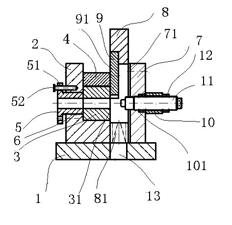
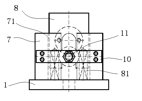
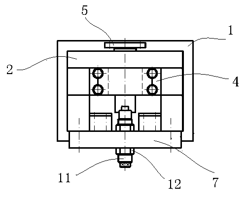
[0032] Embodiment 1: as Figure 1~3 As shown, a cold extrusion cross axis billet blanking mold includes a backing plate 1, a mold base 2 is fixed on the backing plate 1, a lower knife plate 3 is arranged on the mold base 2, and the lower knife plate 3 is connected to the mold through a gland 4. The seat 2 is connected, the rear end of the lower knife plate 3 bears on the adjusting screw 5, the adjusting screw 5 cooperates with the adjusting screw hole 6 on the mold base 2, the rear end of the adjusting screw 5 is provided with a shoulder 51, and the shoulder 51 Lock with the mold base 2 through the pin 52; a guide rail seat 7 is arranged at a certain distance from the front end of the mold base 2, and the bottom of the guide rail base 7 is fixedly connected with the backing plate 1 through screws, and a guide rail 71 is provided on the back of the guide rail base 7. 71 slips are equipped with movable formwork 8, and upper cutter plate 9 is embedded in movable formwork 8, and i...

Embodiment 2

[0039] Embodiment 2: The circular crescent structure is a double crescent structure, that is, two arc-shaped notches 92 are evenly distributed on the circumference of the circular plate, and the two notches can be exchanged for use. When the blade of one of the notches is worn blunt, the upper knife plate can be removed and turned 180° and reinstalled, and another notch can be used to continue blanking, which can save the man-hours of grinding the knife edge, and the rest of the structure is the same as that of embodiment 1, such as Figure 8 shown.

[0040] Applying the mold of the present invention, blanking of round steel with a diameter of ≤φ18mm, the inclination of the end surface of the blank is ≤1°30′, the quality of the incision is significantly improved, and the weight deviation can be controlled to ≤0.0005kg. After data retrieval and comparison, it has reached the advanced level of industrially developed countries , fully meet the weight requirements of high-precisio...


PUM

PropertyMeasurementUnit
diameteraaaaaaaaaa

Abstract

The invention discloses a cold extrusion blanking die for cross shaft blanks. The cold extrusion blanking die comprises a base plate. A die holder is fixed onto the base plate, a lower cutting board is arranged on the die holder and is connected with the die holder by a gland, an adjusting screw tube is abutted to the rear end of the lower cutting board and is matched with an adjusting screw hole in the die holder, and a shoulder of the rear end of the adjusting screw tube is locked by a pin; a guide rail seat is arranged at the front end of the die holder and is fixedly connected with the base plate, guide rails are arranged on the back of the guide rail seat, an upper cutting board is embedded in a movable die plate which is arranged in the guide rails in a sliding fit manner, the outer end of the upper cutting board is in sliding fit with the front end of the lower cutting board, two compression springs are arranged at the lower end of the movable die plate, and the other end of each compression spring is abutted onto the base plate; a back plate is fixedly connected to the front end of the guide rail seat, a regulating screw hole is formed in the middle of the back plate, a blank length control screw is arranged in the regulating screw hole and is locked with the back plate by two locking nuts, and the tail end of the blank length control screw is opposite to the lower cutting board. The cold extrusion blanking die has the advantages that a gap between the upper cutting board and the lower cutting board can be accurately adjusted; a slider of a press machine is prevented from being directly impacted with the upper cutting board, and a vertex position of a bar can be instantly broken; materials can be discharge conveniently, and each cutter of the cold extrusion blanking die is provided with multiple blades.

Description

technical field [0001] The invention belongs to the technical field of blanking dies, in particular to a cold extrusion billet blanking die. Background technique [0002] The cross-shaft universal coupling is an important and necessary transmission part of various styles of cars. The cross shaft is a high-precision cold-extruded forging product with little cutting and no cutting. The journal and end face of the cold-extruded cross shaft do not need Turning processing, after cold extrusion molding, it can be assembled and used only after fine grinding. In order to ensure the quality of forgings after cold extrusion and strictly control the fine grinding allowance, the accuracy of the blank must be controlled within a reasonable range. For example, the universal joint steering cross shaft of a certain car, it is known through calculation and experiments that It is more appropriate that the weight deviation of the billet is within 0.0005kg. Generally, the universal joint stee...

Claims


Application Information

Patent Timeline
Patent Type & Authority Applications(China)
IPC IPC(8): B21D28/14
Inventor 黄春
Owner WANXIANGQIANCHAO CO LTD
Why Eureka
Try Eureka