
Spray tube electrospinning head

An electrospinning and spinning technology, applied in spinneret assemblies, textiles and papermaking, fiber processing, etc., can solve problems such as elongation and thinning, and achieve higher forming speed, higher polarization, and increased Coulomb static. The effect of electricity

Inactive Publication Date: 2013-12-04
常州市亚国新能源科技有限公司
View PDF0 Cites 17 Cited by
  • Summary
  • Abstract
  • Description
  • Claims
  • Application Information

AI Technical Summary

Problems solved by technology

In a traditional single-nozzle electrospinning device, one or more material solutions will form a Taylor cone at the position of the nozzle under the action of a high-strength electrostatic field. As the voltage increases, the fluid surface tension and electrostatic force at the Taylor cone The balance of force is broken, so that a stream of fluid is ejected from the top of the Taylor cone. During the flight of the stream to the collection device, due to the effects of static electricity and fluid viscoelasticity, the stream will be elongated and thinned by several thousand At the same time, the solvent in the stream will volatilize, and the stream will solidify, thereby forming the final solid nanofiber. Under the condition of constant voltage, it is necessary to control the pressure to make the solution flow out of the nozzle in large quantities, and to make the solution under the electric field force Under the action, all the nanofibers will be sprayed onto the receiver. During the whole working process, the solution on the nozzle must not overflow, and the surface area of ​​the solution must be increased. These problems are mutual for the commonly used needles. contradictory and mutually restrictive

Method used


Image

  • Spray tube electrospinning head
  • Spray tube electrospinning head

Examples


Embodiment Construction

[0018] In order to make the content of the present invention more clearly understood, the present invention will be further described in detail below based on specific embodiments and in conjunction with the accompanying drawings.

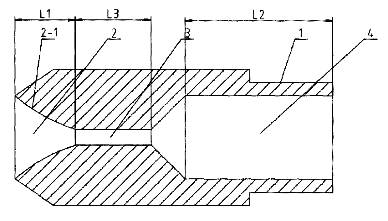
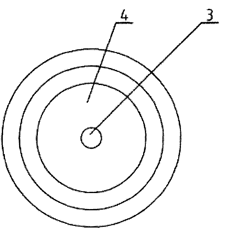
[0019] Such as figure 1 , 2 As shown, a nozzle electrospinning head, which includes an electrospinning head body, the tail of the electrospinning head body is provided with a solution connection part 1, and there are connected trumpet-shaped spinning nozzles in the electrospinning head body from the beginning to the end. 2. The polarization throat hole 3 and the solution cavity hole 4, the diameter of the polarization throat hole 3 is smaller than that of the solution cavity hole 4, and the outer wall of the head of the electrospinning head body is in the shape of a cone whose diameter gradually shrinks outward. Such a structure increases the velocity of the solution passing through the nozzle electrospinning head, increases the degree of polariza...


PUM

PropertyMeasurementUnit
Diameteraaaaaaaaaa
Lengthaaaaaaaaaa
Diameteraaaaaaaaaa

Abstract

The invention discloses a spray tube electrospinning head, and belongs to the field of electrospinning. The spray tube electrospinning head comprises an electrospinning head body, wherein a solution connecting portion is arranged on the tail portion of the electrospinning head body, a horn-shaped spinning nozzle, a polarization throat port and a solution chamber hole are formed in the electrospinning head body in sequence from top to bottom, and are communicated with one another, the inner wall face of the spinning nozzle is a circular-arc curved surface which gradually expands outwards, the port diameter of the polarization throat port is smaller than the hole diameter of the solution chamber hole, the outer wall of the head portion of the electrospinning head body is of a cone shape, and the diameter of the cone gradually decreases outwards. The spray tube electrospinning head can increase the forming speed of a Taylor cone, improve the velocity of a solution when the solution passes through the spray tube electrospinning head, and is better in electric field directivity.

Description

technical field [0001] The invention relates to a nozzle electrospinning head, which belongs to the field of electrospinning. Background technique [0002] At present, electrospinning is a new high-tech technology used to produce continuous fibers with nanometer diameters. In a traditional single-nozzle electrospinning device, one or more material solutions will form a Taylor cone at the position of the nozzle under the action of a high-strength electrostatic field. As the voltage increases, the fluid surface tension and electrostatic force at the Taylor cone The balance of force is broken, so that a stream of fluid is ejected from the top of the Taylor cone. During the flight of the stream to the collection device, due to the effects of static electricity and fluid viscoelasticity, the stream will be elongated and thinned by several thousand At the same time, the solvent in the stream will volatilize, and the stream will solidify, thereby forming the final solid nanofiber....

Claims


Application Information

Patent Timeline
IPC IPC(8): D01D4/02D01D5/00
Inventor 张禄荪汪国锦周寅俊
Owner 常州市亚国新能源科技有限公司
Learn More