Gear speed reduction device, washing machine and washing method thereof

A technology of gear reduction and spur gear, which is applied in the field of washing machines, can solve the problems of inner rotor motor application and insufficient compact structure, and achieve the effects of high transmission efficiency, compact structure and noise reduction

Inactive Publication Date: 2013-12-04
CHANGZHOU XINYA ELECTROMOTOR
View PDF5 Cites 4 Cited by
  • Summary
  • Abstract
  • Description
  • Claims
  • Application Information

AI Technical Summary

Problems solved by technology

Although this structure further reduces the occupied space to a certain extent, because its principle is to use the inner circumferential space of the stator of the outer rotor motor to install the transmission device in the inner diameter space of the stator through the installation parts, it cannot be installed in the inner rotor without inner space. The application on the motor has certain limitations. At the same time, the motor body directly drives the shaft, and then decelerates the drive shaft through the transmission device installed in the inner diameter space of the motor, so it only reduces the occupied space to a certain extent, but the structure It is still not compact enough. Furthermore, when the volume of the transmission device needs to be increased in order to obtain a larger transmission ratio, the outer rotor motor must also increase the volume of the inner diameter to realize this invention. Obviously, this does not solve the substantive technical problem

Method used


Image

  • Gear speed reduction device, washing machine and washing method thereof
  • Gear speed reduction device, washing machine and washing method thereof
  • Gear speed reduction device, washing machine and washing method thereof

Examples


Embodiment 1

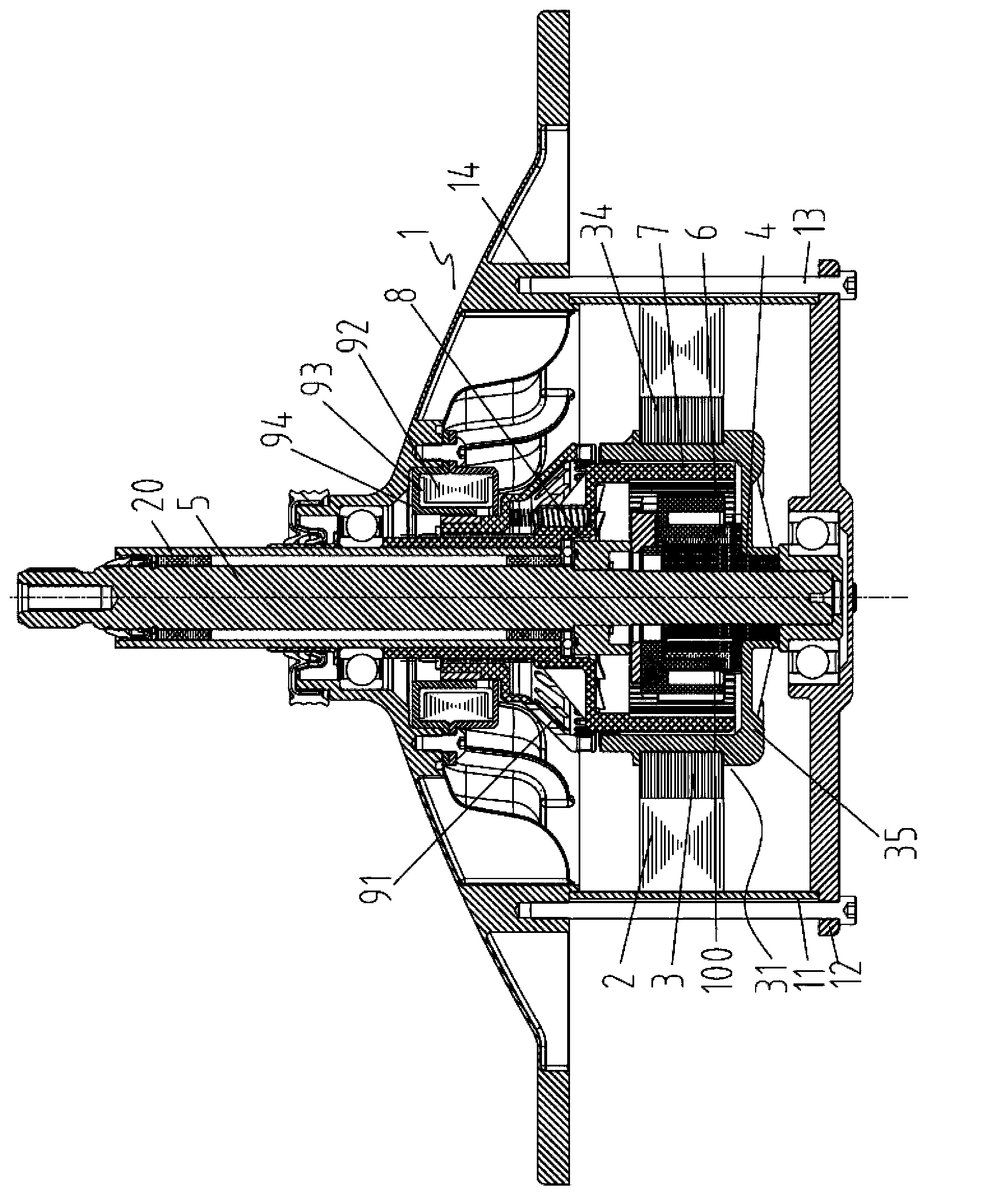
[0061] Such as figure 1 , 2 What is shown is a schematic structural diagram of a sliding block structure in the connecting device in the gear reduction device of the present invention.

[0062] Such as figure 1 As shown, the motor of this embodiment is an inner rotor motor. The housing assembly includes: a cylindrical housing 11 with open ends, a motor end cover 12 connected to the bottom end of the housing 11, and a mounting plate 14 located at the top of the housing and connected to the motor end cover 12 by motor bolts 13, And the housing 11, the motor end cover 12 and the mounting plate 14 enclose an internal space for accommodating the stator 2 and the inner rotor 3 and other components.

[0063] The inner rotor of this embodiment includes a driving frame 31 and a cavity 32 provided inside the driving frame, and a clamping tooth 33 is provided on the top end surface of the driving frame. Specific, such as figure 1 , 12 As shown, the drive frame of this embodiment includes a c...

Embodiment 2

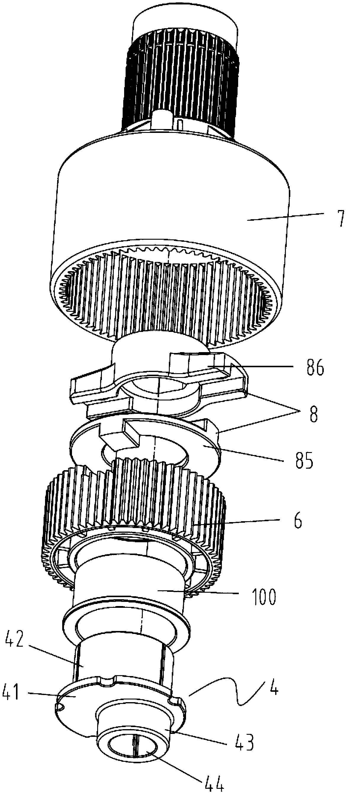
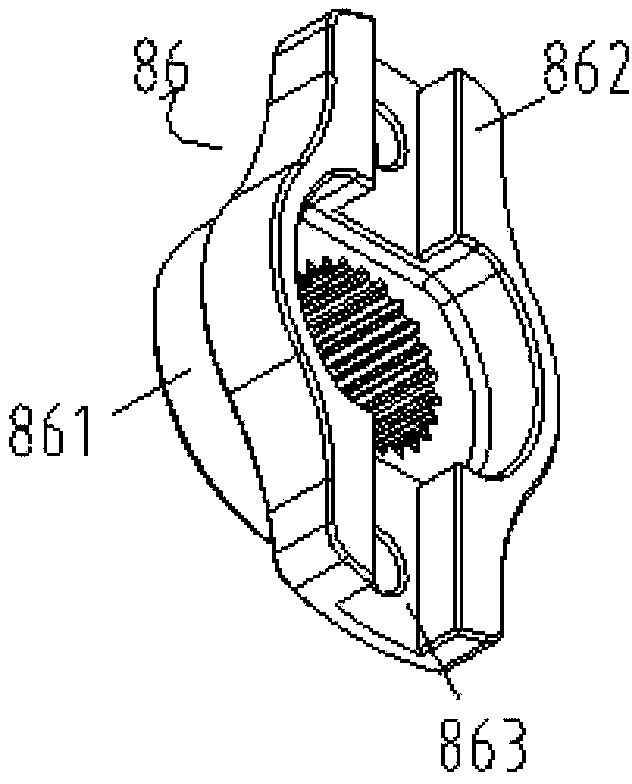
[0094] Such as Figure 7 , 8 Shown is a schematic diagram of the structure of the gear reduction device adopting the connecting disc structure of the present invention.

[0095] Such as Figure 7 It can be seen that the motor in this embodiment is also an inner rotor motor. Among them, an inner rotor with a cavity is arranged in the housing assembly, and a reduction input device, a reduction output part and a clutch device are arranged in the cavity of the inner rotor. The reduction input part includes an eccentric sleeve 4, and the reduction output part includes a positive The gear 6, the ring gear 7 and the connecting device 8. In this embodiment, the connecting device adopts a connecting disc structure.

[0096] In this embodiment, the housing assembly, the clutch device, the eccentric sleeve and the inner ring gear in the deceleration input part and the deceleration output part are the same as those in the first embodiment, and will not be repeated here, and only the connecting...


PUM


Abstract

The invention discloses a gear speed reduction device. The gear speed reduction device comprises a rotating-shaft-free rotator for providing rotating kinetic energy, a speed reduction input component installed in the rotator, a speed reduction output component connected with the speed reduction input component, a first execution component and a second execution component, wherein the first execution component and the second execution component are connected with the speed reduction output component. The speed reduction input component is used for obtaining the rotating kinetic energy and rotating relative to the axis of the rotator by utilizing the obtained rotating kinetic energy; the speed reduction output component is used for outputting power with the rotating speed equal to or lower than the rotating speed of the rotator; and the first execution component and the second execution component are used for rotating under the power effect of the speed reduction output component. A speed reducer is installed in the rotator, and accordingly the volume of the whole gear speed reduction device is compressed. Besides, the gear speed reduction device is simple and compact in structure, saves energy and is small in noise. The invention further provides a washing machine with the gear speed reduction device and a washing method thereof.

Description

Technical field [0001] The present invention relates to the technical field of washing machines, in particular to a gear reduction device for washing machines, a washing machine with the gear reduction device and a washing method thereof. technical background [0002] The washing machine is a machine that removes the stains attached to the laundry through chemical decomposition and mechanical impact. It is mainly driven by a driving device to rotate the pulsator to agitate the water flow and the clothes to rotate to achieve the purpose of washing clothes. At present, the power source of the commonly used driving device is a motor. The output shaft of the motor transmits the torque when the motor rotates to the reduction gear, and then the output shaft of the reduction gear is connected with the pulsator to drive the pulsator to rotate. [0003] The speed of ordinary motors is relatively high. In order to obtain a suitable output speed, the motor needs to be decelerated in practical...

Claims


Application Information

Patent Timeline
Patent Type & Authority Applications(China)
IPC IPC(8): D06F17/08D06F33/06F16H1/32
CPCD06F37/30D06F17/08Y02T10/641F16H1/32F16H2001/325Y10T29/49464F16H1/321F16H3/70F16H37/12F16H2001/323F16H2001/327
Inventor 陈昌
Owner CHANGZHOU XINYA ELECTROMOTOR
Why Eureka
Try Eureka