Membrane type magneto-rheological damper and system

A magnetorheological damper, membrane technology, used in shock absorbers, shock absorbers, springs/shock absorbers, etc., can solve the problems of difficult damping and vibration reduction, affecting the running state of test results, and large piston mass. , to achieve the effect of small inertia, light weight and stable stability

Active Publication Date: 2013-12-04
CHONGQING MATERIALS RES INST
View PDF7 Cites 7 Cited by
  • Summary
  • Abstract
  • Description
  • Claims
  • Application Information

AI Technical Summary

Problems solved by technology

[0002] The magneto-rheological damper is an intelligent damping device. The existing rod-type magneto-rheological damper mostly adopts a piston and cylinder structure, and the piston is mostly a cylinder made of magnetically conductive metal. The viscosity of the magnetorheological medium between the cylinders is used to adjust the output damping force. This type of magnetorheological damper with a cylindrical piston structure has a large mass of the piston and a small gap between the piston and the cylinder. It has a large motion inertia and is difficult to apply to the damping and vibration reduction requirements of high-frequency and small-amplitude vibration occasions; especially for high-precision measuring instruments and other occasions that require high precision, it is necessary to eliminate the high-frequency vibration. interference, otherwise it will affect its detection results and operating status

Method used


Image

  • Membrane type magneto-rheological damper and system
  • Membrane type magneto-rheological damper and system

Examples


Embodiment Construction

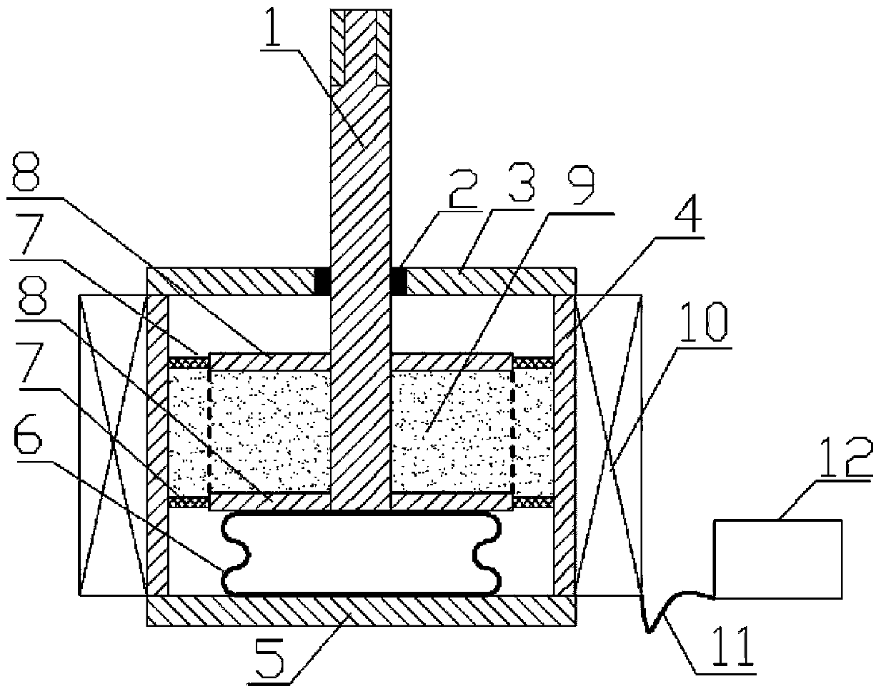
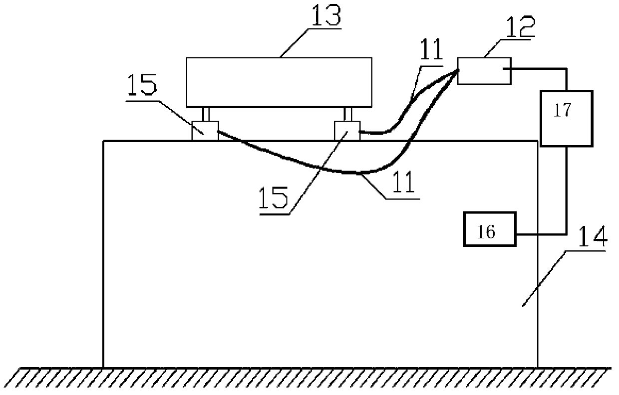
[0024] figure 1 It is a structural schematic diagram of the present invention, figure 2 It is a structural schematic diagram of the damping system of the present invention, as shown in the figure: the film magneto-rheological damper of this embodiment includes a cylinder 4 and a damping assembly located in the cylinder 4, and the damping assembly includes a cylinder 4 located in the cylinder 4 The damping plate 8 arranged side by side along the axial direction of the cylinder body 4 and the damping diaphragm located around the damping plate 8 and sealingly connected between the damping plate and the cylinder body, the damping plate, the damping diaphragm and the cylinder body 4 jointly enclose a Damping chamber, the damping chamber is filled with magnetorheological medium 9; the damping diaphragm is made of flexible or / and elastic material; The damping rod 1 that is fixedly connected to the damping plate in the axial direction, that is to say, the damping rod 1 can be fixedl...


PUM


Abstract

The invention discloses a membrane type magneto-rheological damper and system. The damper comprises a cylinder body and a damping assembly, wherein the damping assembly comprises damping plates and damping membranes, the damping plates are located in the cylinder body and arranged in parallel in the axial direction of the cylinder body, each damping membrane is located around each damping plate and connected between each damping plate and the cylinder body in a sealed mode, a damping cavity is commonly defined by the damping plates, the damping membranes and the cylinder body, and magneto-rheological media are filled into the damping cavity. The damping membranes are made of flexible materials or / and elastic materials, and the damping assembly is provided with a damping rod which extends out of the cylinder body in the axial direction of the cylinder body. The damper further comprises an electromagnet used for controlling the magneto-rheological media, and a control circuit of the electromagnet. The membrane type magneto-rheological damper and system are light in weight and small in inertia, the pulling-back action of the membranes is used and combined with the flexible deformation of the magneto-rheological media in joints of the damping membranes and the damping plates, the coefficient of the flexible deformation is adjustable, therefore, the damping assembly can flexibly react to high-frequency and small-amplitude vibration, the membrane type magneto-rheological damper and system are suitable for detection, production and operation places with high requirements for accuracy, and detection accuracy and operation stability are ensured.

Description

technical field [0001] The invention relates to a magnetorheological damping device, in particular to a magnetorheological damper machine system capable of ensuring that a measuring instrument is not disturbed by external high-frequency and small-amplitude vibrations. Background technique [0002] The magneto-rheological damper is an intelligent damping device. The existing rod-type magneto-rheological damper mostly adopts a piston and cylinder structure, and the piston is mostly a cylinder made of magnetically conductive metal. The viscosity of the magnetorheological medium between the cylinders is used to adjust the output damping force. This type of magnetorheological damper with a cylindrical piston structure has a large mass of the piston and a small gap between the piston and the cylinder. It has a large motion inertia and is difficult to apply to the damping and vibration reduction requirements of high-frequency and small-amplitude vibration occasions; especially for ...

Claims


Application Information

Patent Timeline
Patent Type & Authority Applications(China)
IPC IPC(8): F16F9/53F16F9/32
Inventor 谭和平
Owner CHONGQING MATERIALS RES INST
Why Eureka
Try Eureka