
Multifunctional compression and shear test machine

A testing machine, multi-functional technology, applied in the direction of using stable shear force to test material strength, using stable tension/pressure to test material strength, measuring device, etc. Inaccurate results, troublesome use, etc., to achieve the effect of simple structure, diverse functions, and convenient use

Active Publication Date: 2013-12-04
浙江中科仪器有限公司
View PDF8 Cites 14 Cited by
  • Summary
  • Abstract
  • Description
  • Claims
  • Application Information

AI Technical Summary

Problems solved by technology

This is not only cumbersome to use, but also because the lower pressing plate (104) is not fixed, its bearing capacity is small, and it is easy to move, resulting in inaccurate test results, and it is not possible to test large-weight test pieces

Method used


Image

  • Multifunctional compression and shear test machine
  • Multifunctional compression and shear test machine
  • Multifunctional compression and shear test machine

Examples


Embodiment Construction

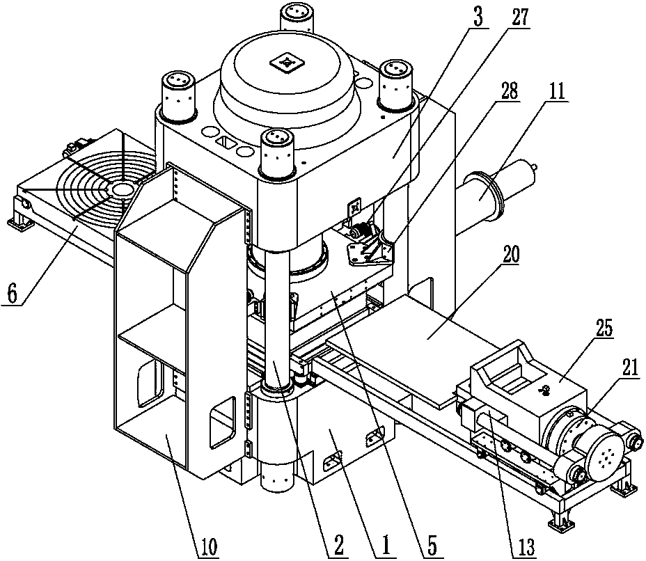
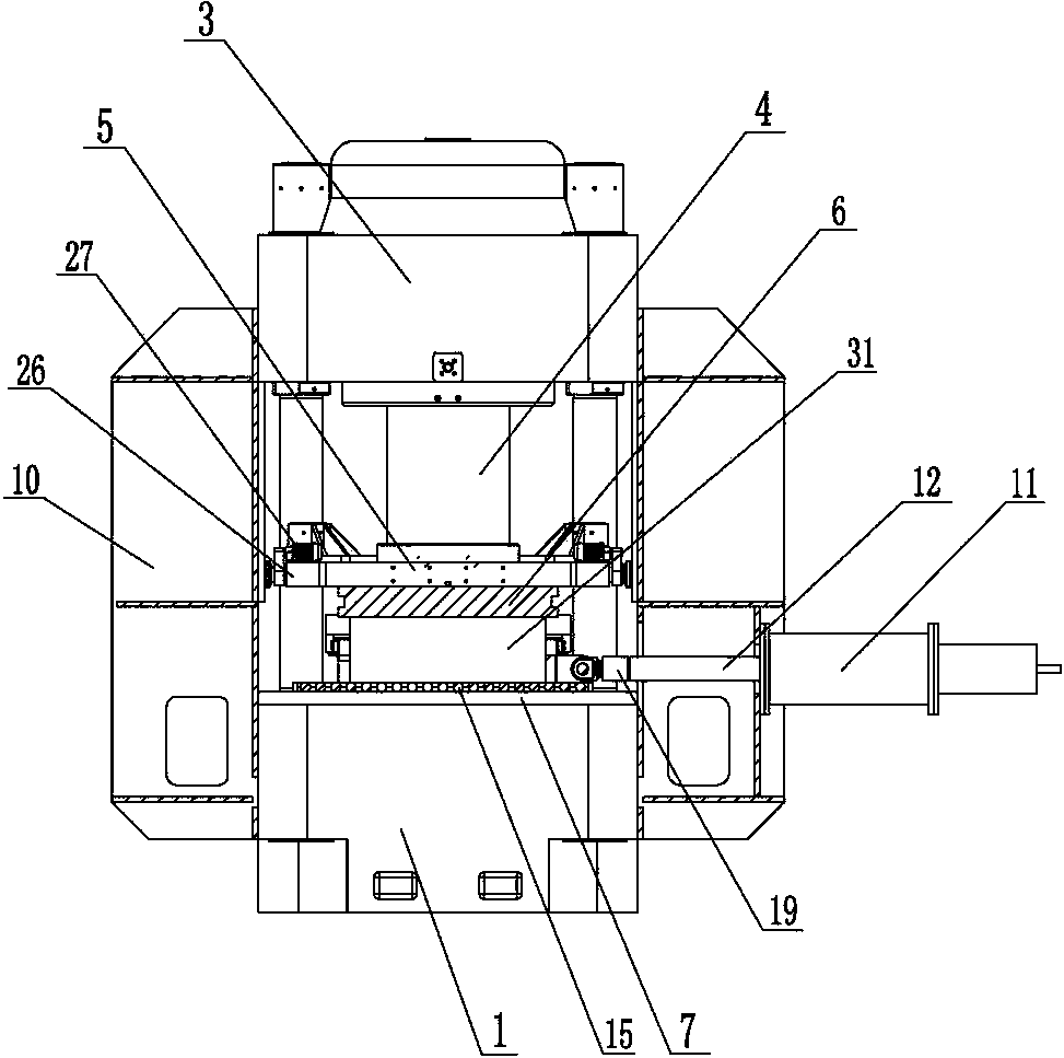
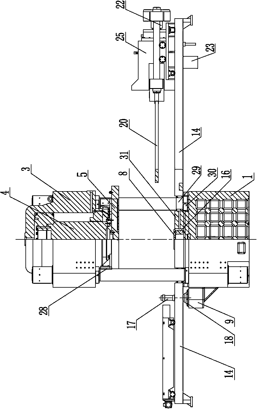
[0023] Please refer to the attached figure 1 to attach image 3 Shown, the present invention is a kind of multifunctional compression-shear testing machine, and it is made up of frame 1, column 2, main oil cylinder 3, main piston rod 4, upper pressing plate 5, dynamic lower pressing plate 6, lower bearing plate 7, backing plate 8 , Corner oil cylinder 9, dynamic support frame 10, dynamic hydraulic oil cylinder 11, dynamic hydraulic piston rod 12 and shear mechanism 13 etc. are composed of several parts.

[0024] Wherein, the column 2 is vertically arranged on the frame 1 . The dynamic support frame 10 is fixed on the front and rear sides of the frame 1 . Guide rails 14 are respectively arranged on the left and right sides of the frame 1, and the dynamic lower pressing plate 6 and the shearing mechanism 13 are respectively arranged on the guide rails 14 and can move along the guide rails 14;

[0025] The main oil cylinder 3 is fixed on the top of the column 2 . The main pis...


PUM


Abstract

The invention relates to a multifunctional compression and shear test machine. The test machine adopts the structure that a vertical column is arranged on a machine frame; a main oil cylinder is fixed at the top of the vertical column; a main piston rod is matched with and driven by the main oil cylinder; an upper compression plate is fixed at the bottom of the main piston rod; guide rails are arranged on the left side and the right side of the machine frame respectively; a dynamic compression plate and a shear mechanism are arranged on the guide rails respectively; a corner oil cylinder is mounted on one side of the machine frame; a lower bearing plate is fixed onto the machine frame; rolling shaft roller sets are arranged on the lower bearing plate; a cushion plate is supported on the rolling shaft roller sets; a pressure sensor is arranged in the cushion plate; dynamic supporting frames are fixed on the front and rear sides of the machine frame; a dynamic hydraulic oil cylinder is mounted on one dynamic supporting frame; one end of a dynamic hydraulic piston rod is connected with the dynamic hydraulic oil cylinder; the other end of the dynamic hydraulic piston rod can be connected with and can drive the dynamic compression plate; a dynamic sensor is arranged on the dynamic hydraulic piston rod. The compression shear test machine can be used for testing static pressure, dynamic pressure, shear force and corner performance, and has the advantages of functional diversity, high bearing capacity, convenience in use and the like .

Description

technical field [0001] The invention relates to mechanical testing equipment, in particular to a multifunctional compression-shear testing machine, which belongs to the technical field of testing equipment. Background technique [0002] The compression-shear testing machine of the prior art is shown in the invention No. 200620042299.8 of the People's Republic of China, which drives the beam (105) and the upper platen (103) to move downward along the column (102) through the drive motor (106) during the pressure test ; At the same time, push the lower platen (104) through the vertical oil cylinder (111) and the vertical piston (112), so that the upper platen (103) and the lower platen (104) are abutted to carry out the static pressure test. Therefore, the above-mentioned compression-shear testing machine cannot The test is performed against dynamic pressure, which creates certain application limitations. [0003] When the above-mentioned compression-shear testing machine per...

Claims


Application Information

Patent Timeline
IPC IPC(8): G01N3/24G01N3/12G01N3/26
Inventor 沈训龙徐继欣谢岳庆吴宇奚勇袁斌汪凡文
Owner 浙江中科仪器有限公司
Learn More