Optical waveguide directional coupler

A technology of directional coupler and optical waveguide, which is applied in the coupling of optical waveguide, light guide, optics, etc., can solve the problems of large coupling effect and coupling distance, low tolerance of directional coupler manufacturing process, etc., to achieve easy manufacturing and improve manufacturing process The effect of high tolerance and process tolerance

Inactive Publication Date: 2013-12-04
HONG FU JIN PRECISION IND (SHENZHEN) CO LTD +1
View PDF4 Cites 5 Cited by
  • Summary
  • Abstract
  • Description
  • Claims
  • Application Information

AI Technical Summary

Problems solved by technology

However, since the coupling effect of the optical waveguide directional coupler is greatly affected by the coupling spacing of adjacent optical waveguides, the process tolerance of the directional coupler is low

Method used


Image

  • Optical waveguide directional coupler
  • Optical waveguide directional coupler

Examples


Embodiment Construction

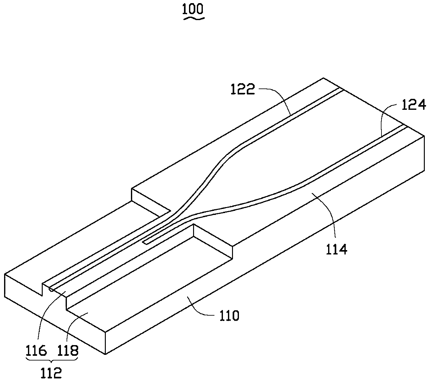
[0012] see figure 1 and figure 2 The optical waveguide directional coupler 100 provided by the embodiment of the present invention includes a substrate 110 and two optical waveguides 122, 124 formed on the substrate 110.

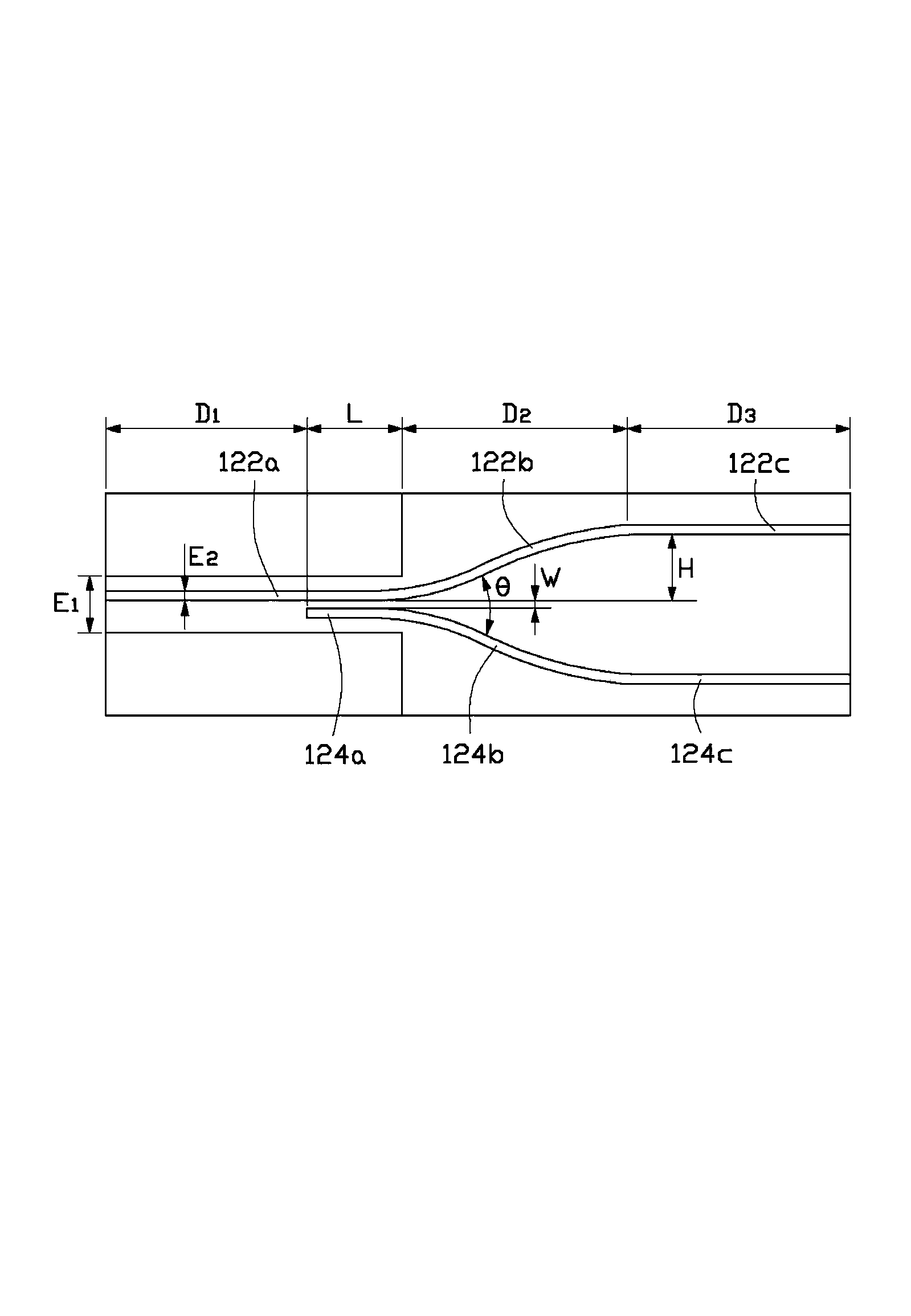
[0013] The base 110 includes a ridge region 112 with a convex cross-section, and a rectangular region 114 adjacent to the ridge region 112 . The raised middle portion of the ridge area 112 forms an inner ridge area 116 , and the upper surface of the inner ridge area 116 is smoothly connected to the upper surface of the rectangular area 114 . The region of the ridge region 112 on both sides of the inner ridge region 116 forms a plate region 118 . Devices such as electrodes (not shown) can be placed on the plate area 118 . The outer edge of the plate area 118 is flush with the outer edge of the rectangular area 114 . In this embodiment, the width E of the inner ridge region 116 1 is 32 μm.

[0014] The two optical waveguides 122 , 124 straddle the inner...


PUM


Abstract

The invention relates to an optical waveguide directional coupler which comprises a substrate and two optical waveguides formed on the substrate. The substrate comprises a ridge area with an inverted-T-shaped section and a rectangle area connected with the ridge area. The ridge area comprises a raised inner ridge area smoothly connected with the rectangle area. The two optical waveguides cross the inner ridge area and the rectangle area, and each optical waveguide comprises a first straight waveguide section located in the inner ridge area, a curved waveguide section and a second straight waveguide section, wherein the curved waveguide section and the second straight waveguide section of each optical waveguide are located in the rectangle area, the curved waveguide section of each optical waveguide is connected with the first straight waveguide section and the second straight waveguide section of each optical waveguide is connected with the corresponding curved waveguide section. The first straight waveguide sections of the two optical waveguides are mutually parallel and a coupling action area is formed between the two first straight waveguide sections. The curved waveguide sections of the two optical waveguides extend outwards in a curved mode. The second straight waveguide sections of the two optical waveguides are mutually parallel.

Description

technical field [0001] The invention relates to an optical waveguide element, in particular to an optical waveguide directional coupler. Background technique [0002] Optical waveguide directional coupler (Light Waveguide Directional Coupler) is an important optical waveguide component in optical communication. It uses the principle of optical coupling between adjacent optical waveguides to realize optical power division or optical multiplexing, thereby achieving directional optical power distribution and control. Compared with other optical waveguide elements, such as Y-branch optical splitters, the optical waveguide directional coupler has the advantages of short element length, low cost and small propagation loss. [0003] The traditional optical waveguide directional coupler is flat and rectangular, which contains two straight optical waveguides parallel to each other. However, since the coupling effect of the optical waveguide directional coupler is greatly affected b...

Claims


Application Information

Patent Timeline
Patent Type & Authority Applications(China)
IPC IPC(8): G02B6/28G02B6/125
Inventor 黄新舜
Owner HONG FU JIN PRECISION IND (SHENZHEN) CO LTD
Why Eureka
Try Eureka